background image

14  www.dimplex.com


Maintenance

partially reflective glass.

!

IMPORTANT: 

Only handle the 

log set by the ember bed.

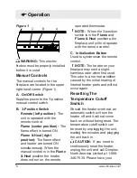
!

NOTE: 

Log set fits tightly into 

firebox, some force may be nec-

essary to remove.
3.  Set log set in front of fire-

place.

4.  Disconnect the log set LED 

wire harness from unit.

5.  Gently pull the flicker rod to 

the right as far as possible 

into the rubber bushing on the 

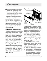
flicker motor shaft (Figure 7).

6.  Unscrew bulbs counter clock-

wise.

7.  Insert new bulbs.
8.  Reconnect the flicker rod and 

the log set LED wire harness.

9.  Install the log set by placing 

the front, bottom edge of the 

ember bed in the track behind 

the front panel. Once in 

place, push down on the back 

edge of the ember bed until 

the rear tab snaps into place 

under the partially reflective 

glass (Figure 7).

!

NOTE: 

Ensure the log set is 

installed tightly under the back 

ledge to prevent light leakage.

10. Replace glass assembly.


Back

Ledge

Log

Ember bed

Rear

Tab

Front

Edge

Side Section

Figure 7

Figure 6

Exploded view to show detail

Flicker Rod

Flicker 

Motor

Bulbs (3)

Summary of Contents for DCF44

Page 1: ...www dimplex com 7210050100R04 IMPORTANT SAFETY INFORMATION Always read this manual first before attempting to install or use this fireplace For your safety always comply with all warnings and safety i...

Page 2: ...gh to emphasize CAUTION Procedures and techniques which if not carefully followed will result in damage to the equipment WARNING Procedures and techniques which if not carefully followed will expose t...

Page 3: ...l void the warranty Please record your model and serial numbers below for future reference model and serial numbers can be found on the Model and Serial Number Label of your fireplace NO NEED TO RETUR...

Page 4: ...ner contact Dimplex Technical Service at 1 888 346 7539 Do not use outdoors IMPORTANT INSTRUCTIONS The electric fireplace is not intended for use in bathrooms laundry areas and similar indoor locatio...

Page 5: ...r supply before performing any cleaning maintenance or relocation of the unit When transporting or storing the unit and cord keep in a dry place free from excessive vibra tion and store so as to avoid...

Page 6: ...receiver is connected Consult the dealer or an experienced radio TV technician for help This device complies with Part 15 of the FCC Rules Operation is subject to the following two conditions 1 This...

Page 7: ...itable location that is not susceptible to moisture and is away from drapes furniture and high traffic CAUTION High temperature risk of fire keep electrical cords drapery furnishings and other combust...

Page 8: ...hen the 3 position switch is in the Flame and Flame Heat positions the fireplace unit will not operate with the remote control C Initialization Button Used to synchronize the remote control NOTE The h...

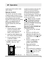
Page 9: ...remote control it is recommended to replace the batteries promptly to maintain full functionality of the remote fireplace The remote control has a battery backup time of only several hours Battery mu...

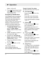
Page 10: ...n button on the unit 5 Press the button on the remote Your remote will now have a different frequency communicating with the fireplace Remote Control Functions All letter references are to Figure 6 B...

Page 11: ...mer reaches zero 0 minutes The Sleep Timer can be can celled at any time by pressing the M button repeatedly until the sleep timer displays noth ing F Flame Heat On Off Button Press the F button to tu...

Page 12: ...To Enable Press I and K at the same time The temperature setting will now be visible again Child Lock Figure 4 1 Depress tab on the battery cover on the back of the re mote control and remove the batt...

Page 13: ...exterior Lower Light Bulb Requirements Quantity of three clear chandelier or candelabra bulbs with an E 12 small socket base 60 Watt rat ing Example GE 60BC or Philips 60 CTC Do not exceed 60 Watts pe...

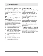
Page 14: ...bulbs counter clock wise 7 Insert new bulbs 8 Reconnect the flicker rod and the log set LED wire harness 9 Install the log set by placing the front bottom edge of the ember bed in the track behind the...

Page 15: ...eplace Figure 5 4 Unscrew bulbs counter clock wise 5 Insert new bulbs 6 Re install upper light bracket 7 Replace glass assembly Glass Cleaning The glass is cleaned in the factory during the assembly o...

Page 16: ...ch products to be free from defects in mate rial and workmanship for a period of 12 months from the date of the first purchase of such product The limited 12 month warranty period also applies to any...

Page 17: ...rs and service agents are also not responsible for IN NO EVENT WILL DIMPLEX OR ITS DIRECTORS OFFICERS OR AGENTS BE LIABLE TO THE PURCHASER OR ANY THIRD PARTY WHETHER IN CON TRACT IN TORT OR ON ANY OTH...

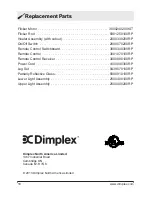
Page 18: ...ker Rod 5901250100RP Heater Assembly with cutout 2000330200RP On Off Switch 2800070200RP Remote Control Switchboard 3000300300RP Remote Control 3001070100RP Remote Control Receiver 3000880100RP Power...

Reviews: