background image


9

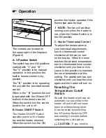
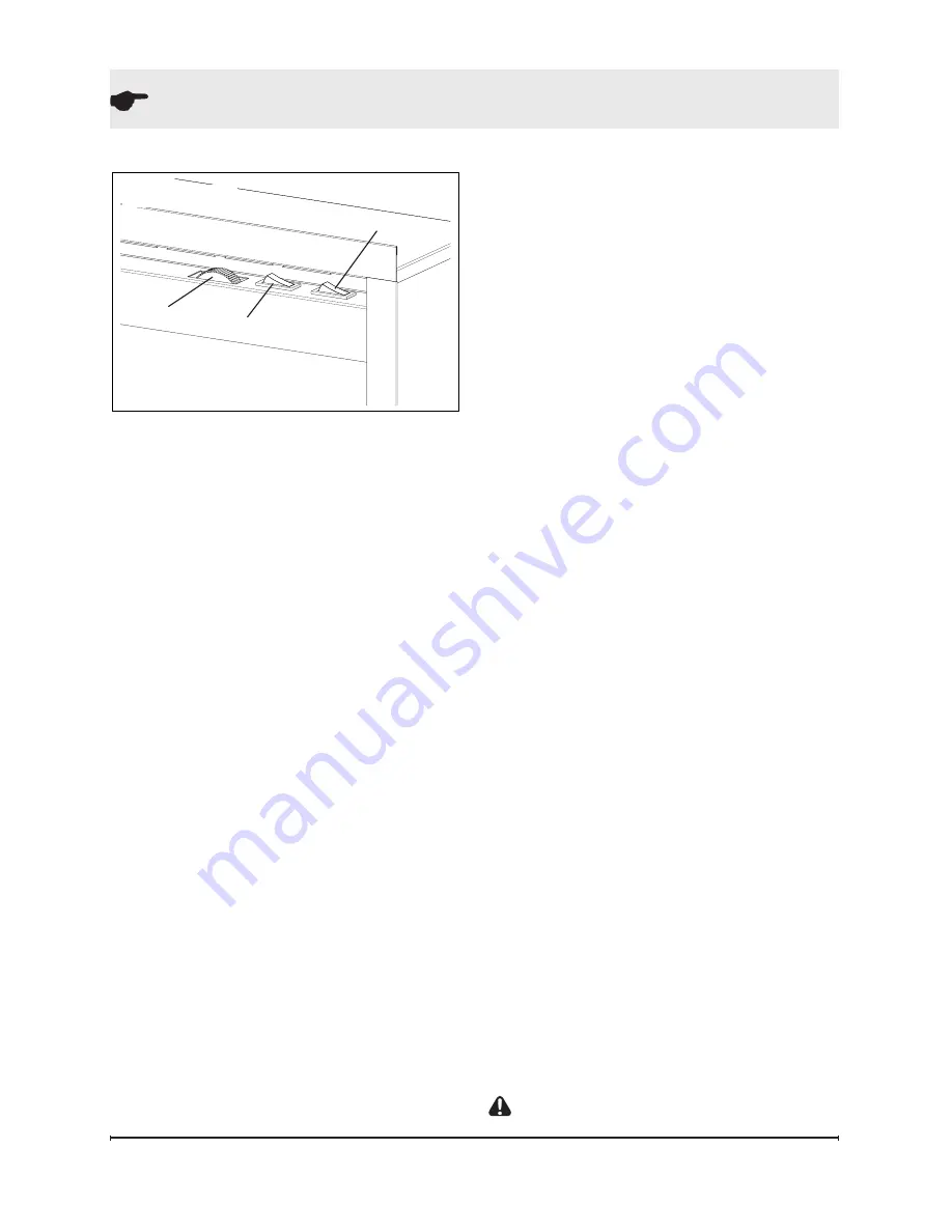
Figure 4

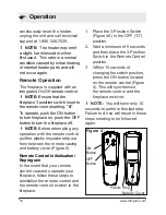
  Operation

The controls are located on 

the upper right of the fireplace.  

(Figure 4)

A.  3-Position Switch

The switch has two ON positions 

marked with " 

I

 " and " 

II

 " .  

The " 

I

 " position is for manual 

operation. In this position the 

built-in remote control is by-

passed. 
The " 

II

 " position is for operating 

the unit with the provided remote 

control.
When in the " 

II

 " position the unit 

is operated with the ON and OFF 

buttons of the remote control.  

When the switch is in the center 

posi

tion the unit is off.

B. Heater ON/OFF Switch 

The Heater ON/OFF Switch 

supplies power to the heater 

fan and the heater element.  

When the switch is in the ON 

position the heater operates if the 

thermostat calls for heat.

!


NOTE: 

The fan will continue 

running even when the heater is 

not, when the Heater Switch is in 

the ON position.

C. Heater Thermostat Control

To adjust the temperature to 

your individual requirements, 

turn the thermostat control 

clockwise all the way to turn 

on the heater.  When the room 

reaches the desired temperature, 

turn the thermostat knob counter 

clockwise until you hear a click.  

Leave in this position to maintain 

the room temperature at this 

setting.  For additional heat, turn 

clockwise until you hear the click 

again and the heater will turn on.

Resetting The 

Temperature Cutoff 

Switch

Should the heater overheat, an 

automatic cut out will turn the 

heater off and it will not come 

back on without being reset.  

It can be reset by switching 

the 3-Position Switch to OFF 

and waiting 5 minutes before 

switching the unit back on.

  CAUTION:  

If you need to 

A

B

C

Summary of Contents for DF2600L

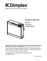
Page 1: ...read this manual first before attempting to install or use this fireplace For your safety always comply with all warnings and safety instructions contained in this manual to prevent personal injury o...

Page 2: ...mphasize CAUTION Procedures and techniques which if not carefully followed will result in damage to the equipment WARNING Procedures and techniques which if not carefully followed will expose the user...

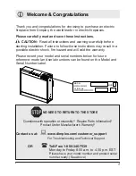
Page 3: ...e hazard and will void the warranty Please record your model and serial numbers below for future reference model and serial numbers can be found on the Model and Serial Number Label NO NEED TO RETURN...

Page 4: ...been dropped or damaged in any manner Return heater to authorized service facility for examination electrical or IMPORTANT INSTRUCTIONS mechanical adjustment or repair Do not use outdoors This heater...

Page 5: ...stall the proper outlet Do not change the plug in any way Always plug heaters directly into a wall outlet receptacle Never use with an extension cord or relocatable power tap outlet power strip Do not...

Page 6: ...esidential installation This equipment generates uses and can radiate radio frequency energy and if not installed and used in accordance with the instructions may cause harmful interference to radio o...

Page 7: ...15 Amp 120 Volt alternating current VAC circuit is required A dedicated circuit is preferred but not essential in all cases A dedicated circuit will be required if after installation the circuit break...

Page 8: ...hat was removed attach the fire box to the mantel Figure 2 NOTE There are no guide holes provided for the L Brackets in the mantel If not installing the unit into a Dimplex mantel the required opening...

Page 9: ...at calls for heat NOTE The fan will continue running even when the heater is not when the Heater Switch is in the ON position C Heater Thermostat Control To adjust the temperature to your individual r...

Page 10: ...attempting any operation with the remote control pull the plastic insulator strip out from between the remote casing and battery cover Figure 5 Remote Control Initialization Reprogram In the event th...

Page 11: ...on Battery Replacement To replace the battery 1 Slide battery cover open on the remote control Figure 5 2 Correctly install one 12 Volt A23 battery in the battery holder 3 Close the battery cover clot...

Page 12: ...e been tested and inspected prior to shipment and subject to the provisions of this warranty Dimplex warrants such products to be free from defects in material and workmanship for a period of 12 month...

Page 13: ...transportation costs Such costs shall be the purchaser s responsibility What Dimplex and its dealers and service agents are also not responsible for IN NO EVENT WILL DIMPLEX OR ITS DIRECTORS OFFICERS...

Page 14: ...ssembly with Cutout 2203610100RP Thermostat with Knob 2600090100RP 3 Position Switch 2800071100RP Heater On Off Switch 2800070700RP Cord Set 4100090203RP Flicker Rod 5902620100RP Partially Reflective...

Reviews: