background image


11

  Operation

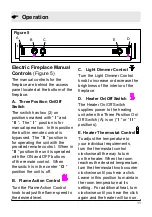
Electric Fireplace Manual 
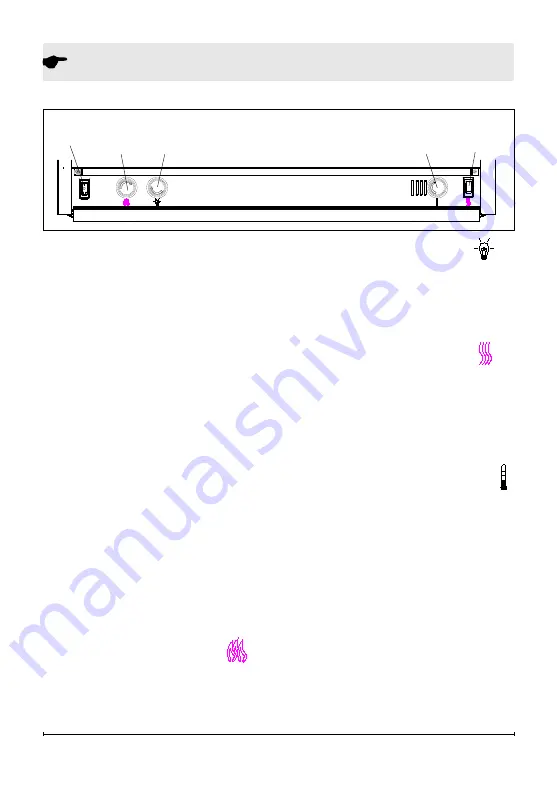
Controls 

(Figure 5)

The manual controls for the 

ireplace are behind the access 

panel located at the bottom of the 

ireplace.

A.  Three Position On/Off 
Switch

The switch has two (2) on 

positions marked with “ 

I

 ” and 

“ 

II 

.  

The “ 

I

 ”  position is for 

manual operation.  In this position 

the built-in remote control is 

bypassed.  The “ 

II 

” position is 

for operating the unit with the 

provided remote control.  When in 

“ 

II 

” position the unit is operated 

with the ON and OFF buttons 

of the remote control.  When 

the switch is in the center “ 


position the unit is off.

B.   Flame Action Control


Turn the Flame Action Control 

knob to adjust the lame speed to 

the desired level. 

C.   Light Dimmer Control 

Turn the Light Dimmer Control 

knob to increase or decrease the 

brightness of the interior of the 

ireplace. 

D.   Heater On/Off Switch  

The Heater on/off switch 

supplies power to the heating 

unit when the Three Position on/

off switch (A) is on (

“ 

I

 ” or “ 

II 

” 

positions)

.

E. Heater Thermostat Control 

To adjust the temperature to 

your individual requirements, 

turn the thermostat control 

clockwise all the way to turn 

on the heater. When the room 

reaches the desired temperature, 

turn the thermostat knob counter 

clockwise until you hear a click. 

Leave in this position to maintain 
the room temperature at its 

setting.  For additional heat, turn 

clockwise until you hear the click 

again and the heater will turn on. 

B

Figure 5

C

A

E

D

Summary of Contents for DF2608

Page 1: ...ON Always read this manual irst before attempting to install or use this ireplace For your safety always comply with all warnings and safety instructions contained in this manual to prevent personal i...

Page 2: ...mphasize CAUTION Procedures and techniques which if not carefully followed will result in damage to the equipment WARNING Procedures and techniques which if not carefully followed will expose the user...

Page 3: ...oid the warranty Please record your model and serial numbers below for future reference model and serial numbers can be found on the model and serial number Label of your ireplace NO NEED TO RETURN TO...

Page 4: ...ord is damaged it must be replaced by the manufacturer or its service agent or a qualiied person in order to avoid a hazard IMPORTANT INSTRUCTIONS Do not operate any unit with a damaged cord or plug o...

Page 5: ...it only as described in this manual Any other use not recommended by the manufacturer may cause ire electric shock or injury to persons Avoid the use of an extension cord Extension cords may overheat...

Page 6: ...r television reception which can be determined by turning the equipment off and on the user is encouraged to try to correct the interference by one or more of the following measures reorient or reloca...

Page 7: ...the risk of ire electric shock or injury to persons always use a licensed electrician Figure 2 Figure 1 Foam Block Cable Ties Front Glass Trim Track Log Set Assembly Fireplace Assembly The only assem...

Page 8: ...way from drapes furniture and high trafic For ease of electrical hook 2 up you may wish to locate the ireplace near an existing outlet refer to noTE 1 store the ireplace in a safe 3 dry and dust free...

Page 9: ...the heater is operating Additional appliances on the same circuit may exceed the current rating of the circuit breaker IMPORTANT If not using a Dimplex mantel the ireplace must be installed in an enc...

Page 10: ...ireplace insert is provided by two 2 spacers Do not install the ireplace insert directly on carpet or similar surfaces which may restrict air circulation If installing the ireplace in a carpeted area...

Page 11: ...lame Action Control knob to adjust the lame speed to the desired level C Light Dimmer Control Turn the Light Dimmer Control knob to increase or decrease the brightness of the interior of the ireplace...

Page 12: ...nd serial number ready when calling Remote Control Figure 6 The ireplace is supplied with an integrated on off remote control NOTE Ensure that the Three Position On Off Switch on the ireplace is set t...

Page 13: ...ht bulbs to cool before touching them to avoid accidental burning of the skin The light bulbs need to be replaced when you notice a dark section of the lame or when the clarity and detail of the log e...

Page 14: ...at the bottom of the mirror Figure 8 IMPORTANT Only handle the log set assembly by the ember bed or plastic grate NOTE Log set assembly its tightly into irebox some force may be necessary to remove Se...

Page 15: ...irror Figure 8 NOTE Ensure the log set Assembly is installed tightly under the bottom edge of the mirror to prevent light leakage Lay unit on it s back and slide 14 Front Glass back into position and...

Page 16: ...ht block bracket 10 Lay unit on it s back slide 11 front glass back into position and attach Trim Glass Cleaning The glass is cleaned in the factory during the assembly operation During shipment insta...

Page 17: ...uch products to be free from defects in material and workmanship for a period of 2 years from the date of the irst purchase of such products as follows a a repair or replacement warranty on defective...

Page 18: ...in lieu of repair or replacement choose to refund the purchase price for such product or part This limited warranty entitles the purchaser to on site or in home warranty services Accordingly Dimplex w...

Page 19: ...rent rates for such services What Dimplex and its dealers and service agents are also not responsible for In no EVEnT WILL DImPLEX or ITs DIrECTors oFFICErs or AGEnTs BE LIABLE To THE PurCHAsEr or AnY...

Page 20: ...otentiometer 3000250100RP Cord set 4100040200RP single Lamp Holder Center Lower 2500150300RP Double Lamp Holder upper and Lower 2500400300RP Mirror 5901210200RP Front Glass 5901220100RP Control Knob 8...

Reviews: