New Wall Construction
1. Select a suitable location that is not susceptible to
moisture and is away from drapes, furniture and high
traffic.
2. Place the fireplace in the desired location to see how
it will look in the room.
3. Mark the desired location on the floor.
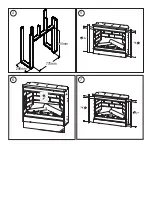
4. Use studs to frame an opening of 680 mm wide X 585
mm high X 229 mm deep.(DF2608) Use studs to frame an
opening of 775 mm wide X 654mm high X 298 mm deep.
(DF3020)
Option #1
The power cord can be run from behind the trim and
along the wall to an outlet near the fireplace.
Option #2
A new outlet can be installed inside the framing
construction. Plug the fireplace into a 10-13Amp/230-
240 Volt outlet. If the cord does not reach you may use
a 3-core type extension cord rated for a minimum of
10 Amps.
Existing Fireplace
1. Seal all drafts and vents with a non-fibrous insulation
material to prevent any chimney debris from falling onto
the fireplace. Do not install into an existing fireplace that
is prone to dampness.
2. Cap the top of the chimney flue to prevent rain from
entering.
3. Plan your electric power supply.
4. The power cord can run along the front of the hearth
to an outlet near the fireplace.
Thermal Safety Cut-out
The built-in overheat cut-out, switches off the appliance
automatically in the event of a fault! Should this occur
switch off the appliance or disconnect the mains plug
from the socket.
Remove any obstructions which may have caused the
overheating. After a short cooling down phase, the
appliance is ready for use again! If the fault should occur
again, contact your local dealer!
WARNING: In order to avoid a hazard due to inadvertent
resetting of the thermal cut-out, this appliance must not be
supplied through an external switching device, such as a
timer, or connected to a circuit that is regularly switched
on and off by the utility.
Maintenance
WARNING:
ALWAYS DISCONNECT FROM THE POWER
SUPPLY BEFORE ATTEMPTING ANY MAINTENANCE.
Light Emitting Diode
This fire is fitted with LED (Light Emitting Diode) lamps. These
LED lamps are maintenance-free and should not require
replacing during the life of the product.
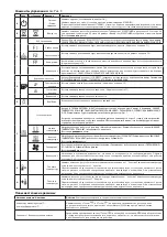
Remote Control -
See Fig. 3
The maximum range of use is ~ 5metres.
NOTE: It takes time for the receiver to respond to the
transmitter.
NOTE: The receiver for the remote control is located in
the display, aim the remote control in this direction when
inputting commands.
Do not press the buttons more than once within two
seconds for correct operation.
Battery Information -
See Fig. 3
1. To activate the remote control remove the clear battery
isolation strip at the base of the remote control, which
is used to ensure your remote control reaches you fully
charged.
2. To replace the remote control battery, turn over the
remote control, and follow the diagram embossed on the
remote control
3. Only use CR2025 or CR2032 size of batteries.
Installing Front Glass-
See Fig. 5, 6 & 7
NOTE: The outer glass is shipped seperate to the firebox.
1. Remove the 6 screws holding the side trims as shown in
Fig. 5. and remove the metal trims.
2. Unpack the glass, ensure it is free from dust and finger
marks and place into position as shown in Fig. 6.
3. Position the metal trims removed in step 1, and secure
with the 6 screws as per Fig. 7
Fitting-
See Fig. 4
IMPORTANT: If not using a Dimplex mantel, the fireplace
must be installed in an enclosure with the following
MINIMUM dimensions(Figure 4).
1. Select a suitable location that is not susceptible to
moisture and is at least 1 meter away from drapes,
furniture and high traffic.
2. Store the fireplace in a safe, dry and dust free location.
3. Clearance for air circulation beneath the fireplace
is provided by two spacers. DO NOT INSTALL FIREPLACE
DIRECTLY ON CARPET OR SIMILAR SURFACES WHICH MAY
RESTRICT AIR CIRCULATION. If installing the fireplace in
a carpeted area, place a one-piece, solid flat surface
under the fireplace. Ensure that all feet rest securely on
this surface!
4. In some jurisdictions this appliance is supplied without
a plug this is to comply with the local regulations. In such
instances this appliance must be installed by a suitably
qualified installer and the means for disconnection must
be incorporated in the fixed wiring in accordance with
the local wiring rules.
Summary of Contents for DF3020-EU
Page 2: ...A B C D E F G H 272mm 802mm 678mm 1 2 3 A C G E B D F H...
Page 3: ...654mm 775mm 298mm 4 5 6 7...
Page 11: ......
Page 15: ......

