14
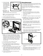
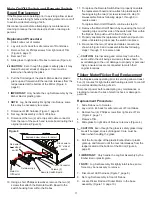
ii) Properly orientate replacement Cutout and attach to
Heater Assembly with screw from step 4.
iii) Disconnect the two (2) wires from the defective
Cutout (one (1) from the Remote Receiver board, and
one (1) from the Heater Element with a piggy-back to
the Motor), noting their original locations.
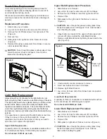
Figure 13
Heater Assembly
Cutout and
screw (1)
Retaining screw
Purifire™
filter
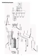
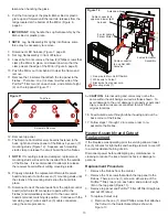
iv) Referring to Figure 14, connect the new Cutout’s two
(2) wires to the Remote Receiver board and Heater
Element and Motor.
v) Follow steps 1 through 3 in reverse order to re-
assemble firebox.
5. To replace Heater Assembly:
i) Remove the one (1) small Phillips screw that attaches
the Cutout to the Heater Assembly as shown in
Figure 13 and stow Cutout safely aside.
ii) Remove the Phillips retaining screw using a short
handled driver. This will release the Heater Assembly
from the firebox (Figure 13).
iii) With Heater Assembly in hand, remove the two (2)
mounting brackets and element baffle. Two (2)
Phillips screws hold each mounting bracket to the
Heater Assembly and four (4) screws attach the baffle
to the element (2 on top and 2 from underneath).
iv) Using screws removed in step iii, attach mounting
brackets and baffle to replacement Heater Assembly.
v) Disconnect one of the wire leads from the defective
Heater Assembly (which are still connected to itself
and the Remote Receiver board) and immediately
connect it to the new Heater Assembly’s terminal,
matching its position. Continue with the remaining
wires using the same procedure (refer to Figure 14).
CAUTION:
Internal wiring and colors may not be the
same within the unit being serviced as those shown. To
avoid damage to the unit, damage to property or personal
injury, ensure wires are reconnected to match their
original locations.
vi) Properly orientate replacement Heater Assembly
into top of firebox and re-attach to the chassis using
screw removed in step i.
vii) Re-attach Cutout to replacement Heater Assembly
using small Phillips screw removed in step 1.
viii) Follow steps 1 through 3 to re-assemble firebox.
Power Cord Replacement
If the fireplace was operating prior to servicing allow at least
10 minutes for light bulbs and heating element to cool off to
avoid accidental burning of skin.
Disconnect power before attempting any maintenance or
cleaning to reduce the risk of electric shock or damage to
persons.
Replacement Procedure:
1. Remove the firebox from the mantel.
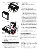
2. Remove the 14 screws that attach the top panel to the
firebox. There are: one (1) screw on either side of the
Purifire™ filter; two (2) on each side; and a total of eight
(8) on the top panel (Figure 11, page 11).
3. Remove top panel and Purifire™ filter (lift filter straight up
and out of firebox).
4. Lay unit on it’s back for safe removal of Front Glass.
5, Remove four (4) Phillips screws from the right side of
Figure 14
Remote
Receiver board
Mounting
brackets (2)
Element
Baffle
screws (4)
①
②
③
Long white wire from Cutout to JP16 terminal
Short white wire from Cutout to bottom Element terminal
then piggy-back to bottom, right terminal of Motor
Red wire from bottom, left Motor terminal to cable connector
①
②
⑥
⑤
④
③
④
⑤
⑥
Black wire from top, right of cable connector to top, front
Element terminal
Blue wire from top Motor terminal to cable connector
Black wire from bottom, right of cable connector to top,
inside Element terminal
Heater
Assembly

