background image

MAINTENANCE


WARNING:  

Disconnect power before attempting any maintenance or cleaning to 

reduce the risk of fire, electric shock or damage to persons.


LIGHT BULB REPLACEMENT


Allow at least 5 minutes for light bulbs to cool before touching bulbs to avoid 
accidental burning of skin.


Light bulbs need to be replaced when you notice a dark section of the flame or 
when the clarity and detail of the log exterior disappears.  There are two bulbs 
under the log set which generate the flames and embers.


TOOL REQUIREMENTS:  

Slot screw driver


HELPFUL HINTS 

It is a good idea to replace all light bulbs at one time if they are close to the end of 
their rated life.  Group replacement will reduce the number of times you need to 
open the unit to replace light bulbs.


LOWER LIGHT BULB REQUIREMENTS:  

Quantity of 3 – 

35 Watt Clear Halogen 

Lamps

, 120 Volt, G9 base.  

DO NOT EXCEED 35 WATTS PER BULB

.


 BULB 

REPLACEMENT


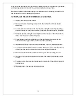
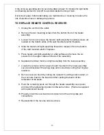
1.  Unplug the unit from the outlet. 
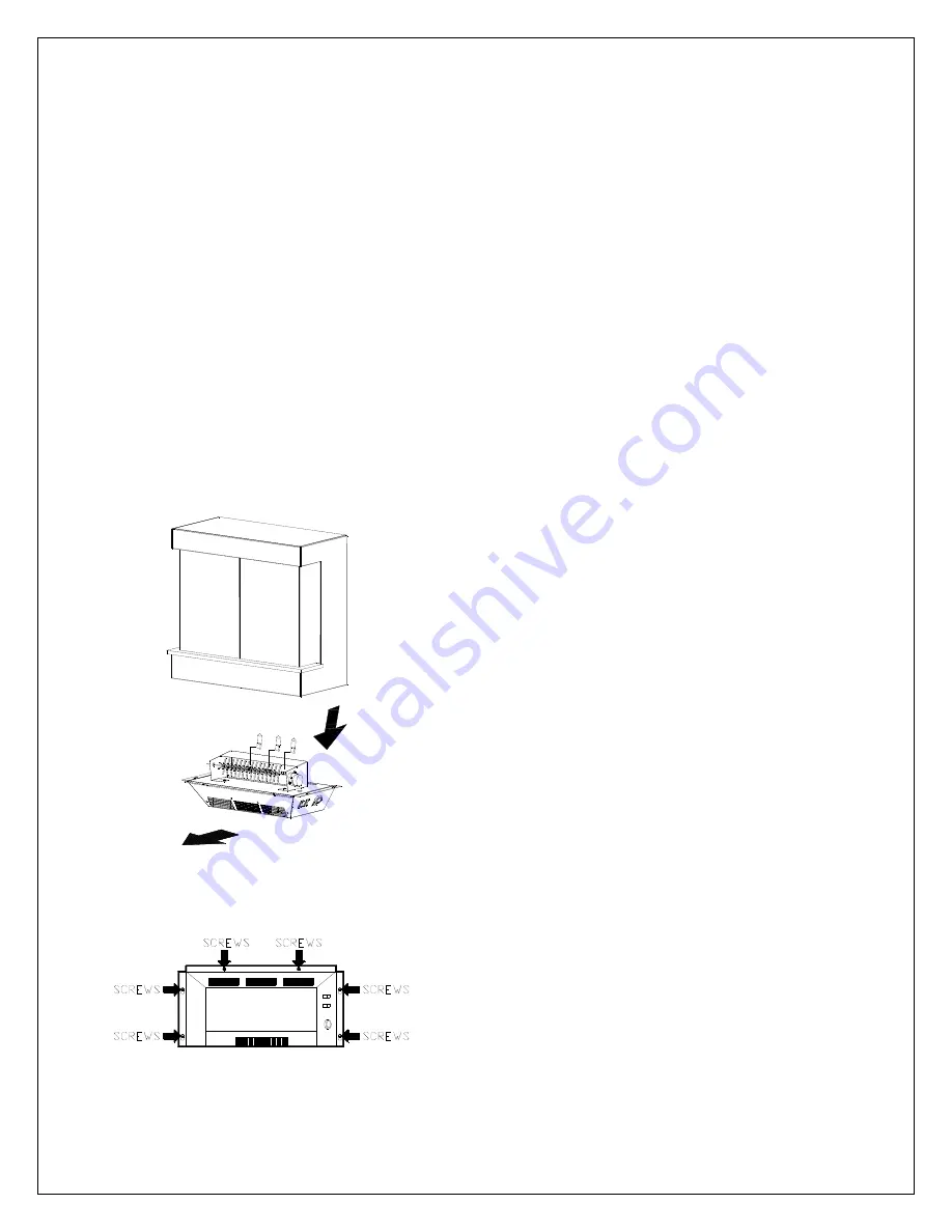
2.  Remove the two mounting screws from the 

bottom front of the heater assembly. 
(FIGURE 3) 

3.  Loosen but do not remove the four heater 

and light assembly mounting screws 
located on the bottom sides of the wall 
mounted electric fireplace.


(FIGURE 3) 

4.  Slide the heater and light assembly forward 

to release it from the bottom of the wall 
mounted electric fireplace


(FIGURE 2). 

5.  Place heater and light assembly on a flat 

surface and examine the bulbs to determine 
which bulb(s) required replacement 

6.  Remove the burnt out bulb(s) by gently 

pulling straight out of socket.  If bulbs are 
difficult to remove from socket move the 
bulb from side to side while pulling being 
careful not to damage the light socket. 

7. Insert new bulb(s). 
8.  Install the heater and light assembly onto 

the four mounting screws. 

9.  Slide the assembly backwards to lock it into 

position. 

10. Tighten the four heater and light assembly 

mounting screws. 

11. Install the two front mounting screws. 
12. Plug in the wall mounted electric fireplace. 


5


FIGURE 2 

FIGURE 3 

Summary of Contents for DFP20-BW1009

Page 1: ...PARTS SERVICE MANUAL EWM COPPER EWM SS DFP20 BW1009 7400300000R01...

Page 2: ...MAIN ON OFF SWITCH 10 TO REPLACE FLAME MOTOR FLAME ROD 11 TO REPLACE HEATER ON OFF SWITCH 12 TO REPLACE HEATER ASSEMBLY 13 TO REPLACE HEATER THERMOSTAT CONTROL 14 TO REPLACE REMOTE CONTROL RECEIVER 1...

Page 3: ...are located on the lower right side of the wall mounted electric fireplace FIGURE 1 A MAIN ON OFF SWITCH The switch has two ON positions marked with and Manual The Manual position is for manual operat...

Page 4: ...an pass through most obstacles including walls It is supplied with one of 243 independent frequencies to prevent interference with other units The frequency code is indicated on the back of the transm...

Page 5: ...LB BULB REPLACEMENT 1 Unplug the unit from the outlet 2 Remove the two mounting screws from the bottom front of the heater assembly FIGURE 3 3 Loosen but do not remove the four heater and light assemb...

Page 6: ...p cloth The glass should be completely dried with a lint free cloth to prevent water spots To prevent scratching do not use abrasive cleaners or spray liquids on the glass surface WALL MOUNTED ELECTRI...

Page 7: ...EXPLODED VIEW EWM COPPER EWM SS DFP20 BW1009 7 01 02 04 05 07 08 11 12...

Page 8: ...00150100RP 5 Heater Assembly 2000230100RP 6 Cordset 4100040200RP 7 Flicker Motor EMC Models 2000140300RP DFP Models 2000220100RP 8 Reflector Rod 5900080600RP 9 Lower Light Harness Incandescent Light M...

Page 9: ...tor F licke r a ssem bly w ire L am ph olde r M oto r B low e r bla de of p lug W ir e o f w ide 24 GA R ed W ire fro m C uto ut B an k E lem ent 2 1 2 1 S w it ch S w it ch 3 0 1 T H E R MO S TA T L...

Page 10: ...t assembly mounting screws located on the bottom sides of the wall mounted electric fireplace 4 Slide the heater and light assembly forward to release it from the bottom of the wall mounted electric f...

Page 11: ...the six screws from the upper sides and back of the assembly 6 Separate the flicker motor and light assembly from the lower assembly 7 Locate and disconnect the wiring connections for the flame motor...

Page 12: ...t assembly mounting screws located on the bottom sides of the wall mounted electric fireplace 4 Slide the heater and light assembly forward to release it from the bottom of the wall mounted electric f...

Page 13: ...ed on the bottom sides of the wall mounted electric fireplace 4 Slide the heater and light assembly forward to release it from the bottom of the wall mounted electric fireplace 5 Place heater and ligh...

Page 14: ...nted electric fireplace 4 Slide the heater and light assembly forward to release it from the bottom of the wall mounted electric fireplace 5 Place heater and light assembly on a flat surface and remov...

Page 15: ...wall mounted electric fireplace 5 Place heater and light assembly on a flat surface and remove the six screws from the upper sides and back of the assembly 6 Separate the flicker motor and light assem...

Page 16: ...from the bottom of the wall mounted electric fireplace 5 Place heater and light assembly on a flat surface and remove the six screws from the upper sides and back of the assembly 6 Separate the flick...

Page 17: ...Problem Flame shudder Probable Cause Defective flame motor Solution Replace flame motor with a new one Service Manual Reference Page 9 Problem Log set dim ember bed not glowing Probable Cause Loose w...

Page 18: ...for loose wiring connections repair replace as necessary If all wiring connections are suitable check heater on off switch heater assembly for proper operation Replace as necessary Service Manual Refe...

Page 19: ...hen the switch is in the OFF position check all wiring for loose connections repair replace as necessary If all wiring connections are suitable check heater on off switch heater assembly for proper op...

Page 20: ...Solution Remove the heater assembly cover and clean the dust out of the blower if noise persists replace heater assembly or see below Service Manual Reference Page 11 Problem Grinding or excessive no...

Page 21: ...sary Service Manual Reference Page 3 Problem Plug or power cord gets warm Probable Cause Normal operation or defective cord Solution Under normal operation with the heater on the plug or cord may get...

Page 22: ...Road Cambridge ON Canada N1R 7G8 1 888 346 7539 www dimplex com In keeping with our policy of continuous product improvement we reserve the right to make changes without notice 2011 Dimplex North Ame...

Reviews: