background image


14

DS7420 
 
If unit was operating prior to servicing allow at least 10 minutes for light bulbs and 
heating element to cool off to avoid accidental burning of skin. 
 
Disconnect power before attempting any maintenance or cleaning to reduce the risk of 
electric shock or damage to persons. 
 

TO REPLACE THE POWER CORD 


1.  Gently place stove on its back on a flat surface. 


2.  Remove the heater cover retaining screws located on the bottom of the stove and 

lower heater and light assembly out onto the floor. 


3.  Remove all of the mounting screws on the heater cover and separate the cover from 

the heater and light assembly. 


4.  Locate and disconnect the power cord wiring connections noting their original 

locations. 


5.  With needle nose pliers grasp the power cord strain relief grommet from inside the 

heater cover and push while twisting to remove. 


6.  Pull the power cord out through the hole in the heater cover. 


7.  Install the new power cord through the hole in the heater cover and connect all of the 

wiring connections in their original locations. 


8.  Install the power cord retaining grommet on the power cord and insert into the hole 

in the heater cover. 


9.  Reassemble in the reverse order as above. 
 

Summary of Contents for DS7420

Page 1: ...PARTS AND SERVICE MANUAL FOR THE 23 STOVE MODEL NUMBER DS7420...

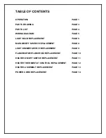
Page 2: ...HT BULB REPLACEMENT PAGE 6 MAIN ON OFF SWITCH REPLACEMENT PAGE 8 LIGHT DIMMER SWITCH REPLACEMENT PAGE 9 FLAME MOTOR FLAME ROD REPLACEMENT PAGE 10 HEATER ON OFF SWITCH REPLACEMENT PAGE 11 HEATER THERMO...

Page 3: ...tlet If the cord does not reach you may use an extension cord rated for a minimum of 1875 watts OPERATION To access the controls go to the back of the stove A MAIN POWER ON OFF SWITCH The main power o...

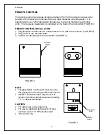
Page 4: ...Plug fireplace cordset into the outlet located on the side of the receiver FIGURE 2 2 Plug receiver into the wall outlet 3 Install a 9 volt battery into the transmitter FIGURE 3 NOTE Fireplace MAIN on...

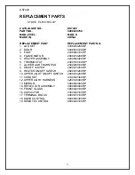
Page 5: ...3 DS7420 2 15 10 13 9 10 7 14 8 1 5 18 11 16 17 6 3 4 19...

Page 6: ...SEMBLY 2200490400RP 6 THERMOSTAT 2300150100RP 7 LOWER LIGHT HARNESS 2500280100RP 8 ON OFF SWITCH 2800070200RP 9 HEATER ON OFF SWITCH 2800070200RP 10 UPPER LIGHT ON OFF SWITCH 2800070200RP 11 CORD SET...

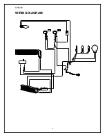
Page 7: ...5 DS7420 WIRING DIAGRAM...

Page 8: ...g set exterior and two bulbs under the log set which generate the flames and embers It is a good idea to replace all of the light bulbs at one time if they are close to the end of their rated life Gro...

Page 9: ...ulbs at one time if they are close to the end of their rated life Group replacement will reduce the number of times you need to open the unit to replace the light bulbs TO REPLACE LOWER LIGHT BULBS 1...

Page 10: ...rear of the top panel 2 Open front door and release the Cams located in the upper corner of both side panels NOTE To release Cams ensure arrow on Cam is facing up 3 Remove top panel 4 Locate the main...

Page 11: ...rear of the top panel 2 Open front door and release the Cams located in the upper corner of both side panels NOTE To release Cams ensure arrow on Cam is facing up 3 Remove top panel 4 Locate the uppe...

Page 12: ...on the bottom of the stove and lower heater and light assembly out onto the floor 3 Remove all of the mounting screws on the heater cover and separate the cover from the heater and light assembly 4 Lo...

Page 13: ...e rear of the top panel 2 Open front door and release the Cams located in the upper corner of both side panels NOTE To release Cams ensure arrow on Cam is facing up 3 Remove top panel 4 Locate the hea...

Page 14: ...located on the bottom of the stove and lower heater and light assembly out onto the floor 3 Remove all of the mounting screws on the heater cover and separate the cover from the heater and light asse...

Page 15: ...e 2 Remove the heater cover retaining screws located on the bottom of the stove and lower heater and light assembly out onto the floor 3 Remove all of the mounting screws on the heater cover and separ...

Page 16: ...oor 3 Remove all of the mounting screws on the heater cover and separate the cover from the heater and light assembly 4 Locate and disconnect the power cord wiring connections noting their original lo...

Reviews: