background image


1

DS7420 


NOTE 

A 15amp, 120 volt circuit is required.  A dedicated circuit is preferred but not essential in 
all cases.  A dedicated circuit will be required if, after installation, the circuit breaker trips 
or fuse blows on a regular basis when the heater is operating.  Additional appliances on 
the same circuit may exceed the current rating of the circuit breaker. 


WARNING 

Ensure the power cord is not installed so that it is pinched or against a sharp edge and 
ensure that the power cord is stored or secured to avoid tripping or snagging to reduce 
the risk of fire, electric shock or injury to persons.


Construction and electrical outlet wiring must comply with local building codes and other 
applicable regulations to reduce the risk of fire, electric shock and injury to persons.


Do not attempt to wire your own new outlets or circuits.  To reduce the risk of fire, 
electric shock or injury to persons, always use a licensed electrician. 


STOVE INSTALLATION


1.  Make sure the units MAIN ON/OFF switch is switched OFF (refer to operating 

instruction section). 


2.  Plug the unit into a 15Amp/120volt outlet.  If the cord does not reach, you may use 

an extension cord rated for a minimum of 1875 watts. 


OPERATION


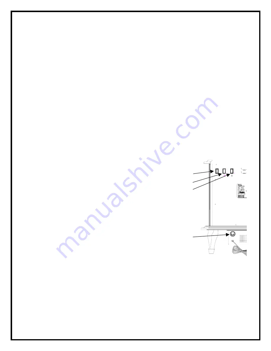
To access the controls, go to the back of the stove. 


A. MAIN POWER ON/OFF SWITCH 

The main power on/off switch supplies power to all stove 
functions (heater & flame). 


B. TOP LIGHT ON/OFF SWITCH 


Controls the light intensity of the log bed display area. 


C. HEATER ON/OFF SWITCH


The heater on off switch supplies power to the heater. 


D. HEATER THERMOSTAT CONTROL 

To adjust the temperature to your individual requirements, 
turn the thermostat control clockwise all the way to turn 
on the heater.  When the room reaches the desired 
temperature, turn the thermostat knob counter clockwise 
until you hear a click.  Leave in this position to maintain 
the room temperature at this setting.  For additional heat, 
turn clockwise until you hear the click again and the heater 
will turn on. 
 

RESETTING THE TEMPERATURE CUTOFF SWITCH 


Should the heater overheat, an automatic cut out will turn the heater off and it will not 
come back on without being reset.  It can be reset by switching the MAIN ON/OFF 
SWITCH to OFF and waiting 5 minutes before switching the unit back on. 


CAUTION 

If you need to continuously reset the heater, unplug the unit and call Dimplex North 
America Limited at 1-800-668-6663. 

A

B

C

FIGURE 1

Summary of Contents for DS7420

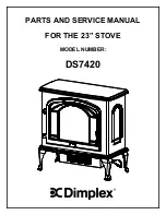
Page 1: ...PARTS AND SERVICE MANUAL FOR THE 23 STOVE MODEL NUMBER DS7420...

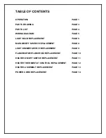
Page 2: ...HT BULB REPLACEMENT PAGE 6 MAIN ON OFF SWITCH REPLACEMENT PAGE 8 LIGHT DIMMER SWITCH REPLACEMENT PAGE 9 FLAME MOTOR FLAME ROD REPLACEMENT PAGE 10 HEATER ON OFF SWITCH REPLACEMENT PAGE 11 HEATER THERMO...

Page 3: ...tlet If the cord does not reach you may use an extension cord rated for a minimum of 1875 watts OPERATION To access the controls go to the back of the stove A MAIN POWER ON OFF SWITCH The main power o...

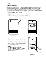
Page 4: ...Plug fireplace cordset into the outlet located on the side of the receiver FIGURE 2 2 Plug receiver into the wall outlet 3 Install a 9 volt battery into the transmitter FIGURE 3 NOTE Fireplace MAIN on...

Page 5: ...3 DS7420 2 15 10 13 9 10 7 14 8 1 5 18 11 16 17 6 3 4 19...

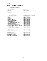
Page 6: ...SEMBLY 2200490400RP 6 THERMOSTAT 2300150100RP 7 LOWER LIGHT HARNESS 2500280100RP 8 ON OFF SWITCH 2800070200RP 9 HEATER ON OFF SWITCH 2800070200RP 10 UPPER LIGHT ON OFF SWITCH 2800070200RP 11 CORD SET...

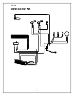
Page 7: ...5 DS7420 WIRING DIAGRAM...

Page 8: ...g set exterior and two bulbs under the log set which generate the flames and embers It is a good idea to replace all of the light bulbs at one time if they are close to the end of their rated life Gro...

Page 9: ...ulbs at one time if they are close to the end of their rated life Group replacement will reduce the number of times you need to open the unit to replace the light bulbs TO REPLACE LOWER LIGHT BULBS 1...

Page 10: ...rear of the top panel 2 Open front door and release the Cams located in the upper corner of both side panels NOTE To release Cams ensure arrow on Cam is facing up 3 Remove top panel 4 Locate the main...

Page 11: ...rear of the top panel 2 Open front door and release the Cams located in the upper corner of both side panels NOTE To release Cams ensure arrow on Cam is facing up 3 Remove top panel 4 Locate the uppe...

Page 12: ...on the bottom of the stove and lower heater and light assembly out onto the floor 3 Remove all of the mounting screws on the heater cover and separate the cover from the heater and light assembly 4 Lo...

Page 13: ...e rear of the top panel 2 Open front door and release the Cams located in the upper corner of both side panels NOTE To release Cams ensure arrow on Cam is facing up 3 Remove top panel 4 Locate the hea...

Page 14: ...located on the bottom of the stove and lower heater and light assembly out onto the floor 3 Remove all of the mounting screws on the heater cover and separate the cover from the heater and light asse...

Page 15: ...e 2 Remove the heater cover retaining screws located on the bottom of the stove and lower heater and light assembly out onto the floor 3 Remove all of the mounting screws on the heater cover and separ...

Page 16: ...oor 3 Remove all of the mounting screws on the heater cover and separate the cover from the heater and light assembly 4 Locate and disconnect the power cord wiring connections noting their original lo...

Reviews: