8 www.dimplex.com
3-POSITION SWITCH REPLACEMENT
Tools Required:
Philips head screwdriver
Flat head screwdriver
WARNING:
If the fireplace was operating prior to ser-
vicing, allow at least 10 minutes for light bulbs and heating
elements to cool off to avoid accidental burning of skin.
WARNING:
Disconnect power before attempting any
maintenance to reduce the risk of electric shock or damage
to persons.
1. Carefully remove the loose media from the front tray, if
applicable.
2. Wall Mount:
Remove the fireplace assembly from the
wall by carefully lifting it upward, releasing it from the
flanges of the wall-mounting bracket. .
Pedestal Mount:
Carefully lay the unit face down on
a flat surface and remove the six screws holding the
pedestal to the unit.
3. Carefully set the unit upright on a flat working surface.
!
NOTE:
If necessary, lay a protective barrier between
the unit and your work surface, (i.e. cloth, cardboard, thick
plastic) to avoid scratching your work surface.
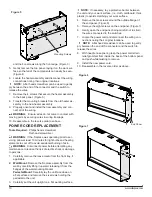
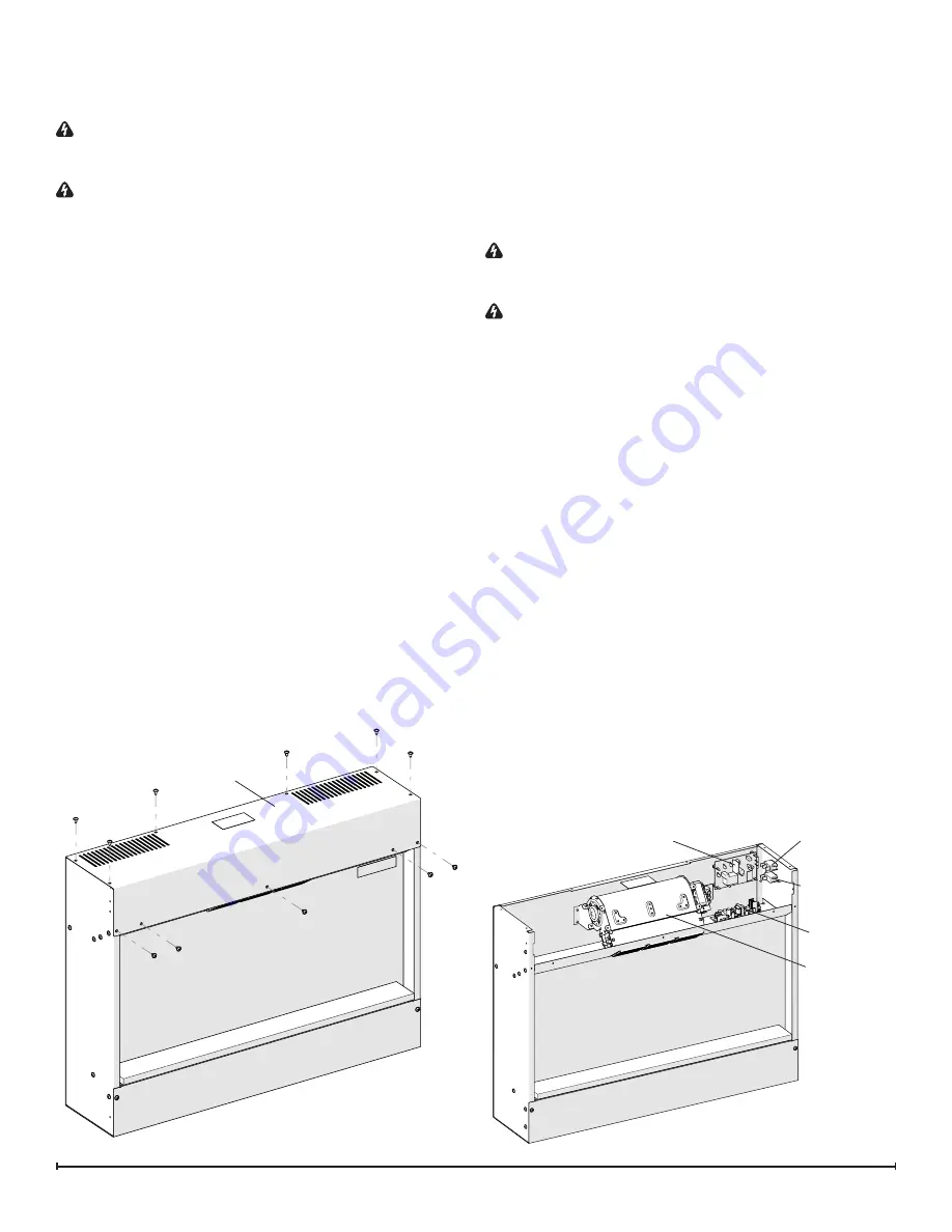
4. Remove the six screws on the top surface of the unit,
and the five screws along the front edge. (Figure 3)
5. Gently remove the top panel, laying it on the work sur-
face so that all of the components can easily be seen.
(Figure 4)
6. Locate the Main Power switch and disconnect the wir-
ing connections noting their original locations.
!
NOTE:
A flat head screwdriver can be used to gently
pry between the end of the connector and the switch to
release the wires.
7. Depress the retainer clips on the rear of the switch and
Figure 3
push the switch out through the opening.
8. Properly orient and insert the new switch and connect
all of the wiring.
9. Reassemble in the reverse order as above.
HEATER ON/OFF SWITCH
REPLACEMENT
Tools Required:
Philips head screwdriver
Flat head screwdriver
WARNING:
If the fireplace was operating prior to ser-
vicing, allow at least 10 minutes for light bulbs and heating
elements to cool off to avoid accidental burning of skin.
WARNING:
Disconnect power before attempting any
maintenance to reduce the risk of electric shock or damage
to persons.
1. Carefully remove the loose media from the front tray, if
applicable.
2. Wall Mount:
Remove the fireplace assembly from the
wall by carefully lifting it upward, releasing it from the
flanges of the wall-mounting bracket. .
Pedestal Mount:
Carefully lay the unit face down on
a flat surface and remove the six screws holding the
pedestal to the unit.
3. Carefully set the unit upright on a flat working surface.
!
NOTE:
If necessary, lay a protective barrier between
the unit and your work surface, (i.e. cloth, cardboard, thick
plastic) to avoid scratching your work surface.
4. Remove the six screws on the top surface of the unit,
and the five screws along the front edge. (Figure 3)
5. Gently remove the top panel, laying it on the work sur-
face so that all of the components can easily be seen.
(Figure 4)
6. Locate the Heat On/Off switch and disconnect the wir-
ing connections noting their original locations.
!
NOTE:
A flat head screwdriver can be used to gently
pry between the end of the connector and the switch to
Figure 4
Top Panel
Remote Control Receiver
3-Position
Switch
Heater On/Off
Switch
LED Driver
Board
Heater
Assembly


