background image


17

 Replacement Parts

Heater Assembly (with Cutout) . . . . . . . . . . . . . . . . . . . . . . . . .

9600560100RP

Front Trim Assembly

 . . . . . . . . . . . . . . . . . . . . . . . . . . . . . . . . .

0441490100RP 

Partially Reflective Glass . . . . . . . . . . . . . . . . . . . . . . . . . . . . . .

5902420100RP

Flame Panel

 . . . . . . . . . . . . . . . . . . . . . . . . . . . . . . . . . . . . . . .

5902400100RP

Power Cord . . . . . . . . . . . . . . . . . . . . . . . . . . . . . . . . . . . . . . . .

4100010800RP

Flicker Motor . . . . . . . . . . . . . . . . . . . . . . . . . . . . . . . . . . . . . . .

2000210500RP

Flicker Rod  . . . . . . . . . . . . . . . . . . . . . . . . . . . . . . . . . . . . . . . .

5901070200RP

Heater On/Off Switch. . . . . . . . . . . . . . . . . . . . . . . . . . . . . . . . .

2800070700RP

3-Position Switch. . . . . . . . . . . . . . . . . . . . . . . . . . . . . . . . . . . .

2800071100RP

Remote Control Receiver  . . . . . . . . . . . . . . . . . . . . . . . . . . . . .

3000380200RP

Remote Control . . . . . . . . . . . . . . . . . . . . . . . . . . . . . . . . . . . . .

3000370900RP

LED Light Assembly  . . . . . . . . . . . . . . . . . . . . . . . . . . . . . . . . .

3000830100RP

LED Driver Board  . . . . . . . . . . . . . . . . . . . . . . . . . . . . . . . . . . .

3000810200RP

Mounting Hardware Kit

 . . . . . . . . . . . . . . . . . . . . . . . . . . . . . . .

9600350100RP

Mounting Bracket. . . . . . . . . . . . . . . . . . . . . . . . . . . . . . . . . . . .

1017130259RP

© 2013 Dimplex North America Limited

Dimplex North America Limited

1367 Industrial Road

Cambridge ON 

Canada N1R 7G8


Summary of Contents for DWF-1326

Page 1: ...this manual first before attempting to install or use this fireplace For your safety always comply with all warnings and safety instructions contained in this manual to prevent personal injury or pro...

Page 2: ...AUTION Procedures and techniques which if not carefully followed will result in damage to the equipment WARNING Procedures and techniques which if not carefully followed will expose the user to the ri...

Page 3: ...d the warranty Please record your model and serial numbers below for future reference model and serial numbers can be found on the Model and Serial Number Label of your fireplace NO NEED TO RETURN TO...

Page 4: ...ged it must be replaced by the manufacturer or its service agent or a qualified person in order to avoid a hazard IMPORTANT INSTRUCTIONS Do not operate any unit with a damaged cord or plug or if the h...

Page 5: ...anual Any other use not recommended by the manufacturer may cause fire electric shock or injury to persons Always plug heaters directly into a wall outlet receptacle Never use with an extension cord o...

Page 6: ...ion between the equipment and the receiver Connect the equipment into an outlet on a circuit different from that to which the receiver is connected Consult the dealer or an experienced radio TV techni...

Page 7: ...tion of your electric fireplace or require service contact customer service 3 The heater may emit a slight harmless odor when first used This odor is a normal condition caused by the initial heating o...

Page 8: ...the risk of fire electric shock and injury to persons Do not attempt to wire your own new outlets or circuits To reduce the risk of fire electric shock or injury to persons Fireplace Installation alw...

Page 9: ...the unit CAUTION High temperature keep electrical cords drapery and other furnishings at least 3 feet 0 9 m from the front of the heater and away from the side and rear 2 The wall mounting bracket mu...

Page 10: ...into the cord storage area mounting holes 4 Place the bubble level on the top of the wall mounting bracket 5 Adjust the wall mounting bracket so the bubble on the level is centered between the two bl...

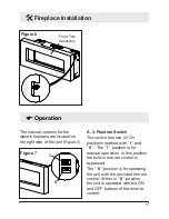
Page 11: ...gure 7 Figure 7 B A A 3 Position Switch The switch has two 2 On positions marked with I and II The I position is for manual operation In this position the built in remote control is bypassed The II po...

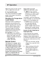
Page 12: ...place the 3 Position Switch in the Remote Control II position 3 Within 10 seconds of When the switch is in the center O position the unit is off B Heat On Off Switch The Heat On Off Switch supplies po...

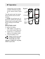
Page 13: ...so will result in these steps needing to be followed again Battery Replacement To replace the battery 1 Slide battery cover open on the remote control Figure 8 2 Install one 1 12 Volt A23 battery in t...

Page 14: ...s these can be removed by dusting lightly with a clean dry cloth To remove fingerprints or other marks the partially reflective glass can be cleaned with a damp cloth The partially reflective glass sh...

Page 15: ...from defects in material and workmanship for a period of 1 year from the date of the first purchase of such products The limited 1 year warranty period also applies to any implied warranties that may...

Page 16: ...ASIS FOR ANY INDIRECT SPECIAL PUNITIVE EXEMPLARY CONSEQUENTIAL OR INCIDENTAL LOSS COST OR DAMAGE ARISING OUT OF OR IN CONNECTION WITH THE SALE MAINTENANCE USE OR INABILITY TO USE THE PRODUCT EVEN IF D...

Page 17: ...10500RP Flicker Rod 5901070200RP Heater On Off Switch 2800070700RP 3 Position Switch 2800071100RP Remote Control Receiver 3000380200RP Remote Control 3000370900RP LED Light Assembly 3000830100RP LED D...

Reviews: