background image

12 

            www.dimplex.com

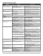
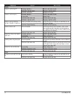
PROBLEM

CAUSE

SOLUTION

Heater

Heater is not turning off

Improper operation

Refer to Operation Section

Defective 3 position switch

Replace 3 position switch

Defective thermostat

Replace thermostat

Heater is not turning on

Improper operation

Refer to Operation Section

Loose wiring

Trace Wiring

Defective heater assembly

Replace heater assembly

Defective 3 position switch

Replace 3 position switch

Heater is turning off after a 

couple of minutes of operation

Build up of dirt/dust in heater assembly

Ensure that exterior intake louvers and firebox cavity 

are free of dirt/dust.

Defective Heater Assembly

Replace Heater Assembly

Heater emits an odor

Normal Operation

Normal operation is when the heater emits an odor 

for a brief period after the heater is initially turned on.  

The heater is burning off any dust accumulated during 

manufacturing or operation.

Defective heater assembly

Replace heater assembly

Heater fan turns on but heater 

lacks heat

Improper operation

Refer to Operation Section

Loose wiring

Trace wiring in unit

Defective heater assembly

Replace heater assembly

Heating element is glowing red

Normal Operation

Small glowing sections of the element are considered 

normal.

Defective heater assembly

If larger glowing sections are causing the heater to trip  

the thermal cutout, unplug unit, discontinue use and 

replace heater assembly.

Heater fan runs continuously

Loose wiring

Trace wiring in unit

Defective momentary switch

Replace momentary switch

Defective heater assembly

Replace heater assembly

Noise

Excessive noise with the heater 

on

Dirty heater assembly

Ensure that exterior intake louvers and firebox cavity 

are free of dirt/dust.

Defective heater assembly

Replace heater assembly

Summary of Contents for DWOP20BR

Page 1: ...North America Limited Dimplex North America Limited 1367 Industrial Road Cambridge ON Canada N1R 7G8 1 888 346 7539 www dimplex com REV PCN DATE 00 1 NOV 13 IMPORTANT SAFETY INFORMATION Always read this manual first before attempting to service this fireplace For your safety always comply with all warnings and safety instructions contained in this manual to prevent personal injury or prop erty dam...

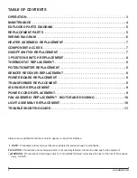
Page 2: ...ose the user to the risk of fire serious injury or death OPERATION 3 MAINTENANCE 4 EXPLODED PARTS DIAGRAM 5 REPLACEMENT PARTS 5 WIRING DIAGRAM 6 HEATER ASSEMBLY REPLACEMENT 7 COMPONENT ACCESS 7 ON OFF SWITCH REPLACEMENT 7 3 POSITION SWITCH REPLACEMENT 8 THERMOSTAT REPLACEMENT 8 POTENTIOMETER REPLACEMENT 8 REMOTE RECEIVER REPLACEMENT 8 POWER BOARD REPLACEMENT 9 TRANSFORMER REPLACEMENT 9 IR SENSOR R...

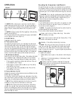
Page 3: ...ation of the flame effect This is normal and should not be a cause for con cern NOTE Always ensure that the appliance is fixed to the wall in a level position The manual controls for the wall mount engine are located on the bottom of the unit Figure 1 A On Off Switch Supplies power to the engine B Thermostat Control To adjust the temperature to your individual requirements turn the thermostat cont...

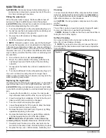
Page 4: ...e or more of the light bulbs have burnt out CAUTION Allow at least twenty minutes for light bulbs to cool before touching bulbs to avoid accidental burning of skin 1 Leaving the flame effect on remove the rock media tray and water tank and lift out the top cover Figure 3 2 View the lamps from a distance in front of the fire and observe which lamp needs to be changed 3 Turn the unit off and unplug ...

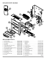
Page 5: ...ly 9600670100RP 10 Water Reservoir Sump 0441380100RP 11 Fan Assembly 5300300100RP 12 Fan Housing Assembly 9600540100RP 13 Fan Filter 8600300100RP 14 Transducer 3800040100RP 15 Power Cord Mod 0 A 9600385500RP Mod B 9600740100RP 16 On Off Switch 9600383500RP 17 3 Position Switch 9600383600RP 18 Transformers 9600690100RP 19 Mounting Hardware Kit 9600700100RP 20 Potentiometer 9600640100RP 21 Thermosta...

Page 6: ...6 www dimplex com WIRING DIAGRAM ...

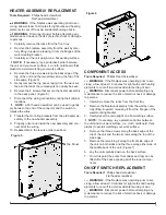
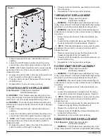
Page 7: ...ll of the wiring 10 Reassemble in the reverse order as above Figure 5 COMPONENT ACCESS Tools Required Phillips Head Screwdriver WARNING If the fireplace was operating prior to ser vicing allow at least 10 minutes for light bulbs and heating elements to cool off to avoid accidental burning of skin WARNING Disconnect power before attempting any maintenance to reduce the risk of electric shock or dam...

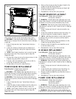
Page 8: ...ements to cool off to avoid accidental burning of skin WARNING Disconnect power before attempting any maintenance to reduce the risk of electric shock or damage to persons 1 Follow Component Access instructions before pro ceeding 2 Locate the thermostat and disconnect the wiring con nections noting their original locations Figure 8 NOTE A flat head screwdriver can be used to gently pry between the...

Page 9: ...prior to ser vicing allow at least 10 minutes for light bulbs and heating elements to cool off to avoid accidental burning of skin WARNING Disconnect power before attempting any maintenance to reduce the risk of electric shock or damage to persons 1 Follow Component Access instructions before pro ceeding 2 Locate the transformer and disconnect the wiring con nections noting their original location...

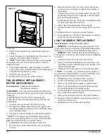
Page 10: ... new motor and reas semble the remainder of the cassette in reverse order from the instructions above If replacing the housing remove the 3 screws attaching the base to the cassette Figure 6 8 Attach new fan housing base to the cassette 9 Transfer the filter from the old housing to the new hous ing 10 Reinstall the fan motor and reconnect the wire 11 Re assemble the remainder of the cassette in re...

Page 11: ...he ON I position but mode Switch B has not been pressed Figure 2 Press Switch B once for flame effect Figure 2 Low water level Check the water tank is full and there is water in the sump Water in unit is too cold Allow water to warm to room temperature If using distilled or reverse osmosis water unit will not produce a consistent mist Add 1 8 tsp of table salt to water reservoir to intro duce elec...

Page 12: ... the heater is initially turned on The heater is burning off any dust accumulated during manufacturing or operation Defective heater assembly Replace heater assembly Heater fan turns on but heater lacks heat Improper operation Refer to Operation Section Loose wiring Trace wiring in unit Defective heater assembly Replace heater assembly Heating element is glowing red Normal Operation Small glowing ...
Reviews: