background image

11

Additional Information

After Sales Service

Your product is guaranteed for one year from the date of purchase. Within this period, we undertake to 
repair or exchange this product free of charge (excluding transducer discs & subject to availability) provided 
it has been installed and operated in accordance with these instructions. Your rights under this guarantee 
are additional to your statutory rights, which in turn are not affected by this guarantee.

The transducer is a consumable item and may need to be replaced through time, depending on its usage. 
Replacement transducers can be purchased from your supplier.
The transducer has a 12 month warranty period.

CAUTION:

 Do not use if the heater’s mains power lead is damaged. Such use may cause a hazard. If 

damaged, the mains power lead must be replaced by the manufacturer or its authorised dealer. 

Recycling

For electrical products sold within the European Community - At the end of the electrical products 
useful life it not be disposed of with household waste. Please recycle where facilities exist. Check 
with your Local Authority or retailer for recycling advice in your country.

Patent / Patent Application

Products within the Optimyst range are protected by one or more of the following patents and patent 
applications:

Great Britain GB2460259B, GB2475794B, GB2418014, EP2029941, GB2436212, GB2402206B
United States US8413358, US8136276, US7967690, US8574086
Russia RU2434181
European EP2029941, EP2315976, EP1787063 (A1), EP2388527
China CN101883953A, CN102105746A, CN101057105 (A), CN101438104
Australia AU2009248743A1, AU2007224634
Canada CA2725214, CA2579444, CA2645939

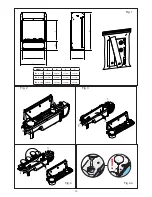
4.  Disconnect the electrical connector, located on the right side of the sump. (Fig.5) .
5.  Release the right sump locking tabs by turning 90º. This allows the sump to be lifted completely from its 

location. (Fig. 11)

6.  Gently lift up the sump, taking care to keep level so as not to spill any water. Sit the assembly in the sink.
7.  Release the left sump locking tabs by turning 90º, then lift off the Nozzle. (Fig.3)
8.  Lift out the transducer and carefully tilt, as shown, so that the liquid drains out of the sump. (Fig.13)
9.  Put a small amount of washing up liquid into the sump, and using the supplied brush, gently clean all 

surfaces in the sump and gently clean the transducer including the metal discs located in the top grooved 
surface. (Fig.14)

10. When cleaned, thoroughly rinse the sump with clean water to remove all traces of washing up liquid.
11. Clean the Nozzle with the brush and flush out thoroughly with water. (Fig.15)
12. Reverse the above steps to reassemble.

Air filter

1.  Gently lift out the fuelbed and place carefully on the ground.
2.  Gently slide the air filter upwards out of its plastic holder. (Fig.16)
3.  Gently rinse with water in the sink and dry with fabric towel before returning.
4.  Replace the filter making sure that the coarse black filter is facing the front of the fire.

Summary of Contents for ENG56-400 E

Page 1: ...lerte rom eller sporadisk bruk RO Acest produs este adecvat exclusiv spa iilor bine ventilate sau utiliz rii ocazionale CZ Tento v robek je vhodn pouze do dob e izolovan ch prostor nebo k p le itostn...

Page 2: ...ly switch on off the appliance provided that it has been placed or installed in its intended normal operating position and they have been given supervision or instruction concerning use of the applian...

Page 3: ...tion of the flame effect This is normal and should not be a cause for concern If this product experiences a power surge for whatever reason the product may cut out This is a normal safety feature and...

Page 4: ...cing brackets as a guide There is to be an air vent at the front of the structure of at least 88cm2 It is essential to ensure that air can circulate into the appliance otherwise the Opti myst flame ef...

Page 5: ...o put fire in to standby mode This will be indicated by one beep REMOTE CONTROL The remote control is packed with 2 AA batteries in a bag Lift off the battery cover on the back of the remote control a...

Page 6: ...ress either up or down on the home screen until the display shows the temperature you require Thermal Safety Cut out A thermal safety cut out is incorporated in the fan heater to prevent damage due to...

Page 7: ...or to adjust the off Hour time press Enter to Confirm Press v or to adjust the off Minute time press Enter to Confirm Press Enter to modify Programme P2 follow steps 5 12 Press to skip to P3 Press En...

Page 8: ...emperature set point Press Enter to confirm Press BACK three times to return to the home screen Adaptive Start The built in electronics in this appliance hava a learning function with regards to how l...

Page 9: ...will automatically activate when you use the Timer Mode Maintenance GENERAL TIPS Only use filtered tap water in this appliance Always ensure that the appliance is sitting on a level surface If you in...

Page 10: ...pins from the lamp holder Fig 4 and 4a 7 Replace with an OPTIMYST 12V 45W Gu5 3 base 8 beam angle coloured lamp Purchased from www dimplex co uk spares 8 Carefully insert the two pins of the new lamp...

Page 11: ...2402206B United States US8413358 US8136276 US7967690 US8574086 Russia RU2434181 European EP2029941 EP2315976 EP1787063 A1 EP2388527 China CN101883953A CN102105746A CN101057105 A CN101438104 Australia...

Page 12: ...transducer might be dirty Fig 14 The wire from the Transducer Unit is sitting over the metal disc Increase the level of fire with the remote control Clean the Metal Disc with soft brush supplied Fig 1...

Page 13: ...13 Fig 4 Fig 4a Fig 2 Fig 3 Fig 1 X W 255 168 Y H MODEL H W X Y ENG56 400 700mm 490mm 413mm 395mm ENG68 400 823mm 490mm 413mm 517mm ENG56 600 700mm 646mm 569mm 395mm...

Page 14: ...14 Fig 5 Fig 5a Fig 5b Fig 6 Fig 7 Fig 8...

Page 15: ...15 Fig 10 Fig 11 Fig 12 Fig 13 Fig 14 Fig 9...

Page 16: ...16 Fig 15 Fig 16...

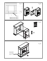
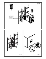
Page 17: ...17 x8 100cm2 ENG56 400 A 440mm B 386mm ENG68 400 A 440mm B 509mm ENG56 600 A 566mm B 386mm 1m Fig 17 Fig 18 Fig 19 Fig 20...

Page 18: ...18 88cm 2 2 2 1m B C A 100cm2 100cm2 100cm2 Fig 21 Fig 22 Fig 23 X...

Page 19: ...19...

Page 20: ...N SO30 2DF TEL 0844 879 3588 FAX 0844 879 3583 WEBSITE www dimplex co uk Republic of Ireland Tel 01 8424833 c GDC Group Ltd All rights reserved Material contained in this publication may not be reprod...

Reviews: