8
www.dimplex.com
!
NOTE:
Using a flat head screwdriver gently pry be
-
tween the end of the connector and the heater to release
the wires.
!
NOTE:
If high limit cut-out was not ordered with the
heater assembly, remove the small screw which secures
the cutout to the heater assembly housing just below the
elements and attach it to the new heater. If a high limit cut-
out has been sent with the heater, disconnect the 2 wires
leading from the high limit cutout from their locations on the
terminal box.
Connect these wires onto the new heater assembly
12.
and back on to the heater switch and circuit board in
the same positions as the original connections.
Fit the air deflector over the elements with the screwing
13.
flanges on the left, right and out towards the front.
Raise the bottom end of the fireplace up several inches
14.
to re-attach the 2 heater assembly brackets.
!
NOTE:
If you are working on a raised surface, the unit
can be slid toward you so that the bottom is exposed and
the holes can be easily accessed
Fit the heater assembly with the deflector vent cover
15.
(but not the heater assembly housing cover), into the
housing area in the lower area of the fireplace.
Feed a screw into one of either the left or the right the
16.
bracket holes from behind the back panel, then line up
the hole on the rubber bracket gasket as well as the
hole on the bracket itself over the screw and tighten the
screw.
After attaching the first screw, do the same on the
17.
opposite bracket. Alternate sides after each of the 4
screws.
Secure the deflector cover to the bottom with 4 screws
18.
Align the plastic mounting plate on the mounting flange
19.
on the motor side of the heater/fan assembly, and
guide the fan-housing cover into place.
Secure the 3 screws to the heater assembly housing
20.
cover to fan assembly mounting flanges on the front of
the heater assembly: 1 on the left; 2 on the right side.
!
NOTE:
The left side with the plastic mounting plate
requires a washer to be used together with the screw.
!
NOTE:
Remember to slide the mesh metal screening
between the deflector cover and the vent located on the
bottom of the fireplace.
Secure the 4 screws to the bottom heater assembly
21.
housing cover from underneath.
Secure the switch-housing panel with the 3 screws
22.
from the bottom and 2 screws from the housing below
the flicker motor.
Turn the unit over and lay it on to its front to secure
23.
the remaining 6 screws from behind the back panel; 4
for the fan-housing panel and 2 for the switch-housing
panel.
Re-assemble the firebox in reverse order.
24.
FLICKER MOTOR REPLACEMENT
Tools Required:
Phillips Head Screwdriver
CAUTION:
Follow “Preparation for Service” instructions
before proceeding.
WARNING:
If the fireplace was operating prior to ser
-
vicing allow at least 10 minutes for light bulbs and heating
elements to cool off to avoid accidental burning of skin.
WARNING:
Unplug or disconnect power at the circuit
breaker before attempting any maintenance to reduce the
risk of electric shock or damage to persons.
Carefully turn the fireplace back over, onto it’s back
1.
with the switches and bottom closest to you.
Locate the switch-housing cover on the lower, interior
2.
right side. Remove the 2 screws, which secure the
upper housing cover, just below the flame motor, to the
electrical/switch-housing cover beneath it.
Remove 3 screws which secure the switch housing
3.
from the bottom panel
Remove (1) screw, which secures the switch housing
4.
from the lower part of the side panel, and (1) on the
bottom, front right corner.
Remove the switch housing cover out of the chassis
5.
and set it aside.
Remove the flicker rod from the flicker assembly by
6.
pulling and twisting the rubber gasket piece on the rod
away from the flame motor.
Disconnect the wiring connections of the flame motor
7.
and the capacitor from the terminal block noting their
original locations.
!
NOTE:
Using a flat head screwdriver gently pry be
-
tween the end of the connector and the motor to release
the wires.
!
NOTE:
The capacitor will be re-used. Be sure to note
which terminal and wires it’s connected to for re-installation.
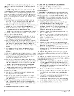
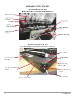
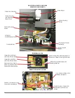
(See Assembly Part Pictures)
Remove the 2 screws that secure the flicker motor to
8.
the flicker bracket and remove the motor, sliding the
wires out through the protective sheath held by the wire
ties and through the opening in the flicker wire housing
cover just below the motor.
Mount the new flicker motor to the flicker bracket.
9.
Feed the wires from the new motor back through open
-
10.
ing in the flicker wire housing cover and protective
sheath.
Connect the wires and the capacitor back into the ter-
11.
minal block in their original configuration.
Re-attach the flicker rod to the motor by pushing the
12.
rubber gasket on the rod over the flicker motor shaft.
Re-assemble the firebox in reverse order.
13.

