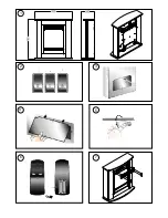
Controls -
see Fig. 2
Three switches provide a choice of heat settings. The appliance
is in standby mode when the mains lead is plugged in. This is
indicated by the red neon behind the flame effect screen. The
two selector switches are in the ON position when the side with
the markings on (i.e.
I
, or
II
) are pushed in.
Push button switch 1
Controls the electricity supply to
the heater and flame effect.
If both selector switches 2 and 3 are in the OFF position, the
product works on flame effect only.
Selector switch 2 (I)
Provides 750W heat output
Selector switch 3 (II)
Provides 1500W output with switch
2
also
pressed.
Remote control - see Fig. 6
The maximum range of use is ~ 10metres/32.8 ft.
The remote will turn the fire on and off only.
Warning: It takes time for the receiver to respond to the
transmitter.
Do not press the buttons more than once within two seconds
for correct operation.
Battery Information - see Fig. 6
1. Slide open the battery cover on the back of the remote control.
2. Install two AAA batteries into the remote control, being careful
to insert the battery as indicated in the battery compartment of
the handset.
3. Replace the battery cover.
Discard Leaking Batteries
Dispose of batteries in the proper manner according to provincial
and local regulations.
Any battery may leak electrolyte
- if mixed with a different battery type,
- if inserted incorrectly,
- if all the batteries are not replaced at the same time,
- if disposed of in a fire,
- if an attempt is made to charge a battery not intended to be
recharged.
Disposal of Used Batteries.
Batteries may contain hazardous substances which could be
endangering to the environment and human health.
The symbol marked on the battery and /or packaging indicates
that used batteries should not be treated as municipal waste.
Instead they should be left at the appropriate collection point
for recycling.
By ensuring used batteries are disposed of correctly, you will help
to prevent potential negative consequences on the environment
and human health. The recycling of materials will help to conserve
natural resources.
For more information please contact your local authority.
Thermal Safety Cut-out
The built-in overheat cut-out switches off the appliance
automatically in the event of a fault! Switch off the appliance or
disconnect the mains plug from the socket.
Remove any obstructions which may have caused the
overheating. After a short cooling down phase, the appliance
is ready for use again! If the fault should occur again, see your
local dealer!
WARNING: In order to avoid a hazard due to inadvertent
resetting of the thermal cut-out, this appliance must not be
supplied through an external switching device, such as a timer,
or connected to a circuit that is regularly switched on and off by
the utility.
Maintenance
WARNING: ALWAYS DISCONNECT FROM THE POWER
SUPPLY BEFORE ATTEMPTING ANY MAINTENANCE.
Lamp Replacement - see Fig.3, Fig.4 and Fig.5
The lamps are located behind the back panel. To gain access to
the lamp, the screws indicated in
Fig. 3
which secure the back
panel, must be removed.
Remove and slide out panel as indicated on
Fig. 4
.
Replace with a 60W E14 SES Clear candle lamp. Take care not
to over-tighten the lamp.
Refit the back panel and secure with the screws.
Wall fixing
- see
Fig. 1
The appliance should be securely fixed to the wall using the wall
plugs and screws supplied for block walls.
Note – for studded walls special fasteners are required, see
diagram for recommended position of fixing screws.
Remove wall fixing before attempting any maintenance.
Cleaning
WARNING – ALWAYS DISCONNECT FROM THE POWER
SUPPLY BEFORE CLEANING THE HEATER.
For general cleaning use a soft clean duster – never use abrasive
cleaners. The glass viewing screen should be cleaned carefully
with a soft cloth.
DO NOT use proprietary glass cleaners.
To remove any accumulation of dust or fluff the soft brush
attachment of a vacuum cleaner should occasionally be used
to clean the outlet grille of the fan heater.
It is possible to clean the inner glass and logset by removing
the outer glass panel. To remove the outer glass, remove the
4 screws holding the grille in position, (see
Fig.7
), remove the
grille and lift clear the outer glass.
Refit the outer glass in reverse of above.
WARNING: do not operate the product without the grille and outer
glass in position as this may effect the operation of the heater.


