background image

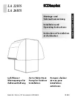
Luft/Wasser-
Wärmepumpe für 
Außenaufstellung

LA 22HS
LA 26HS

Air-to-Water Heat 
Pump for Outdoor 
Installation

Pompe à chaleur 
air-eau pour 
installation 
extérieure

Montage- und 
Gebrauchsanweisung

Deutsch

English

Français

Instructions d’installation 
et d’utilisation

Installation and
Operating Instructions

Bestell-Nr. / Order no. / N

o

 de commande : 452158.66.10

FD 8902

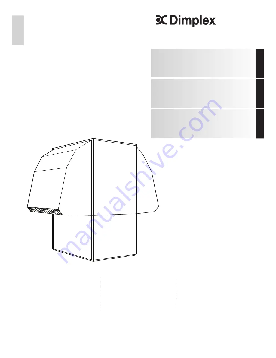
Summary of Contents for LA 22HS

Page 1: ...Pump for Outdoor Installation Pompe à chaleur air eau pour installation extérieure Montage und Gebrauchsanweisung Deutsch English Français Instructions d installation et d utilisation Installation and Operating Instructions Bestell Nr Order no No de commande 452158 66 10 FD 8902 ...

Page 2: ......

Page 3: ...mpenregler DE 4 4 Transport DE 4 5 Aufstellung DE 5 5 1 Allgemein DE 5 5 2 Kondensatleitung DE 5 6 Montage DE 5 6 1 Allgemein DE 5 6 2 Heizungsseitiger Anschluss DE 5 6 3 Elektrischer Anschluss DE 6 7 Inbetriebnahme DE 6 7 1 Allgemein DE 6 7 2 Vorbereitung DE 6 7 3 Vorgehensweise DE 6 8 Reinigung Pflege DE 7 8 1 Pflege DE 7 8 2 Reinigung Heizungsseite DE 7 8 3 Reinigung Luftseite DE 8 8 4 Wartung ...

Page 4: ...ebrauch gilt als nicht bestimmungsgemäß Dazu zählt auch die Beachtung der zugehörigen Produktschriften Än derungen oder Umbauten am Gerät sind zu unterlassen 1 3 Gesetzliche Vorschriften und Richtlinien Bei der Konstruktion und Ausführung der Wärmepumpe wurden alle entsprechenden EG Richtlinien DIN und VDE Vorschriften eingehalten siehe CE Konformitätserklärung Beim elektrischen Anschluss der Wärm...

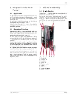
Page 5: ...eizwasser abgegeben Dabei wird die elektrische Energie eingesetzt um die Wärme der Umwelt auf ein höheres Temperaturniveau anzuheben Da die der Luft entzogene Energie auf das Heizwasser übertragen wird bezeichnet man dieses Gerät als Luft Wasser Wärmepumpe Die Luft Wasser Wärmepumpe besteht aus den Hauptbauteilen Verdampfer Ventilator und Expansionsventil sowie den ge räuscharmen Verdichtern dem V...

Page 6: ...i Funktionsweise und Handhabung des Wärmepumpenreglers sind in der dazu beiliegenden Gebrauchsanweisung beschrie ben 4 Transport ACHTUNG Die Wärmepumpe darf beim Transport nur bis zu einer Neigung von 45 in jeder Richtung gekippt werden Der Transport zum endgültigen Aufstellungsort sollte mit Holz rost erfolgen Das Grundgerät bietet einerseits die Transport möglichkeit mit Hubwagen Sackkarre o Ä o...

Page 7: ...läu che werden nach unten aus dem Gerät geführt Beim Anschluss an die Wärmepumpe muss an den Übergängen mit einem Schlüssel gegengehalten werden Bevor die heizwasserseitigen Anschlüsse der Wärmepumpe er folgen muss die Heizungsanlage gespült werden um eventuell vorhandene Verunreinigungen Reste von Dichtmaterial oder Ähnliches zu entfernen Ein Ansammeln von Rückständen im Verflüssiger kann zum Tot...

Page 8: ...endienst durchgeführt werden Unter bestimmten Bedingungen ist damit eine Verlängerung der Gewährleistung verbunden vgl Garan tieleistung 7 2 Vorbereitung Vor der Inbetriebnahme müssen folgende Punkte geprüft wer den Alle Anschlüsse der Wärmepumpe müssen wie in Kapitel 6 beschrieben montiert sein Im Heizkreislauf müssen alle Schieber die den korrekten Fluss des Heizwassers behindern könnten geöffne...

Page 9: ...eifen Um Störungen durch Schmutzablagerungen im Wärme austauscher der Wärmepumpe zu vermeiden ist dafür zu sor gen dass der Wärmeaustauscher in der Heizungsanlage nicht verschmutzen kann Sollte es dennoch zu Betriebsstörungen wegen Verschmutzungen kommen ist die Anlage wie unten an gegeben zu reinigen 8 2 Reinigung Heizungsseite Sauerstoff kann im Heizwasserkreis insbesondere bei Verwen dung von S...

Page 10: ...ten einmal jährlich durch den Betreiber auf Dichtheit ge prüft werden Die Dichtheitsprüfung ist zu dokumentieren und mindestens 5 Jahre aufzubewahren Die Kontrolle ist gemäß Verordnung EG Nr 1516 2007 von zertifiziertem Personal durchzuführen Zur Dokumentation kann die Tabelle im Anhang verwendet wer den 9 Störungen Fehlersuche Diese Wärmepumpe ist ein Qualitätsprodukt und sollte störungs und wart...

Page 11: ...16 3 3 3 20 4 3 9 20 2 3 7 3 4 Schall Leistungspegel dB A 66 66 3 5 Heizwasserdurchfluss bei interner Druckdifferenz m h Pa 1 8 3000 2 3 6000 1 8 3000 2 7 8200 3 6 Luftdurchsatz m h 8000 8000 3 7 Kältemittel Gesamt Füllgewicht Typ kg R404A 3 3 R404A 3 7 R134a 2 7 R134a 3 1 3 8 Schmiermittel Gesamt Füllmenge R404A Typ Liter R404A Polyolester POE 1 9 Polyolester POE 1 9 Typ Liter R134a Polyolester P...

Page 12: ...gene Teile und Geräte Anlagenmängel die auf nicht vom Lieferer bezogene Teile zurückzuführen sind fallen nicht unter den Garantieanspruch Sofern der Mangel nicht beseitigt werden kann oder die Nach besserung von uns abgelehnt oder unzumutbar verzögert wird wird der Hersteller entweder kostenfreien Ersatz liefern oder den Minderwert vergüten Im Falle einer Ersatzlieferung behalten wir uns die Gelte...

Page 13: ...4 4 Transport EN 4 5 Set up EN 5 5 1 General Information EN 5 5 2 Condensed Water Pipe EN 5 6 Installation EN 5 6 1 General Information EN 5 6 2 Heating System Connection EN 5 6 3 Electrical Connection EN 6 7 Start up EN 6 7 1 General Information EN 6 7 2 Preparation EN 6 7 3 Procedure EN 6 8 Maintenance Cleaning EN 7 8 1 Maintenance EN 7 8 2 Cleaning the Heating System EN 7 8 3 Cleaning the Air S...

Page 14: ... other use beyond that intended by the manufacturer is prohibited This includes the user s abiding by the manufacturer s product brochures Please refrain from tampering with or altering the device 1 3 Legal Regulations and Directives The construction and design of the heat pump complies with all relevant EU directives DIN VDE regulations see CE declaration of conformity When connecting the heat pu...

Page 15: ...xchanger Electrical energy is used to raise the temperature of the heat in the environment to a higher level Because the energy extracted from the air is transferred to the heating water this type of device is called an air to water heat pump The air to water heat pump consists of the main components evaporator ventilator and expansion valve as well as the low noise compressors liquifier and elect...

Page 16: ... these instructions together with the neces sary fixing accessories The enclosed operating instructions describe the function and use of the heat pump controller 4 Transport ATTENTION When transporting the heat pump ensure that it is not tilted more than 45 in any direction Use a wooden pallet for transporting the heat pump to the final in stallation location The basic device can be transported wi...

Page 17: ...nwards direction Use a spanner to firmly grip the transi tions when connecting the heat pump Before connecting the heating water system to the heat pump the heating system must be flushed to remove any impurities residue from sealants etc Any accumulation of deposits in the liquifier could cause the heat pump to completely break down For systems in which the heating water flow can be shut off via ...

Page 18: ...after sales service technician authorised by the manufacturer This may be a condition for extending the guaran tee see Warranty Service 7 2 Preparation The following items need to be checked prior to start up The heat pump must be fully connected as described in Chapter 6 All valves that could impair the proper flow of the heating water in the heating circuit must be open The air intake and air ou...

Page 19: ...mp ensure that the heat exchanger in the heating system can not be contaminated In the event that operating malfunc tions due to contamination still occur the system should be cleaned as described below 8 2 Cleaning the Heating System The ingress of oxygen into the heating water circuit may result in the formation of oxidation products rust particularly if steel components are used These products ...

Page 20: ...e operator according to ES842 2006 The leak proof testing is to be documented and archived for a minimum of 5 years The test is to be carried out by certified per sonnel only according to EG Nr 1516 2007 The attached table can be used as a basis for the documentation 9 Faults Trouble Shooting This heat pump is a quality product and is designed for trouble free and maintenance free operation In the...

Page 21: ...35 2 kW 16 5 3 5 16 3 3 3 20 4 3 9 20 2 3 7 3 4 Sound power level dB A 66 66 3 5 Heating water flow with an internal pressure differential of m h Pa 1 8 3000 2 3 6000 1 8 3000 2 7 8200 3 6 Air flow rate m h 8000 8000 3 7 Refrigerant total filling weight type kg R404A 3 3 R404A 3 7 R134a 2 7 R134a 3 1 3 8 Lubricant total filling weight R404A type litres R404A Polyolester 1 9 Polyolester 1 9 type li...

Page 22: ...lation FR 5 5 1 Remarques d ordre général FR 5 5 2 Ecoulement des condensats FR 5 6 Montage FR 5 6 1 Remarques d ordre général FR 5 6 2 Branchement côté installation de chauffage FR 5 6 3 Branchements électriques FR 6 7 Mise en service FR 6 7 1 Remarques d ordre général FR 6 7 2 Préparation FR 6 7 3 Procédures à suivre FR 6 8 Nettoyage entretien FR 7 8 1 Entretien FR 7 8 2 Nettoyage côté chauffage...

Page 23: ...e comme non con forme La documentation accompagnant les produits doit égale ment être prise en compte Toute modification ou transformation de l appareil est interdite 1 3 Dispositions légales et directives Lors de la construction et de la réalisation de la pompe à chaleur toutes les normes CE et prescriptions DIN et VDE concernées ont été respectées voir déclaration de conformité CE Les normes VDE...

Page 24: ...faire passer la chaleur de l environnement à un niveau de température plus élevé Comme l énergie extraite de l air est transmise à l eau de chauf fage on appelle cet appareil pompe à chaleur air eau La pompe à chaleur air eau comprend les principaux compo sants comme l évaporateur le ventilateur et la vanne d expan sion ainsi qu un compresseur peu bruyant un condenseur et une commande électrique A...

Page 25: ...teur et ces instructions Mode de fonctionnement et utilisation du régulateur de pompes à chaleur sont décrits dans les instructions d utilisation livrées avec l appareil 4 Transport ATTENTION Lors du transport l angle d inclinaison de la pompe à chaleur ne doit pas dépasser 45 quel que soit le sens Le transport vers l emplacement définitif devrait s effectuer à l aide d une palette en bois L appar...

Page 26: ... par le bas Pour raccorder la pompe à chaleur il faudra contre bloquer au niveau des traversées à l aide d une clé vant de procéder au raccordement de la pompe à chaleur côté eau de chauffage l installation de chauffage doit être rincée pour éliminer d éventuelles impuretés et les restes éventuels des ma tériaux d étanchéité ou autres Une accumulation de dépôts di vers dans le condenseur est susce...

Page 27: ...doit être effectuée par un service après vente agréé par le construc teur Ceci permet de prolonger la garantie sous certaines condi tions 7 2 Préparation Avant la mise en service il est impératif de procéder aux vérifica tions suivantes tous les raccordements de la pompe à chaleur doivent être réalisés comme décrit au chapitre 6 dans les circuits de chauffage et d eau glycolée toutes les vannes su...

Page 28: ... ils attaquent les surfaces Pour éviter des dysfonctionnements dus à des dépôts dans l échangeur thermique de la pompe à chaleur il faut veiller à ce que l échangeur de chaleur dans l installation de chauffage ne puisse pas s encrasser Si des dysfonctionnements dus à des impuretés devaient se produire malgré cette mesure l installa tion devra être nettoyée comme indiqué ci après 8 2 Nettoyage côté...

Page 29: ...teur doit pouvoir fournir la preuve que l étanchéité a été vérifiée et conserver cette preuve pendant au moins 5 ans Selon la directive européenne n 1516 2007 CE ce contrôle doit être effectué par du personnel qualifié Vous pouvez utiliser le ta bleau annexe pour votre dossier 9 Défaillances recherche de pannes Cette pompe à chaleur est un produit de qualité et elle devrait fonctionner sans dysfon...

Page 30: ... 2 3 7 3 4 Niveau de puissance sonore dB A 66 66 3 5 Débit d eau de chauffage avec pression diff int m h Pa 1 8 3000 2 3 6000 1 8 3000 2 7 8200 3 6 Débit d air m h 8000 8000 3 7 Fluide frigorigène poids au remplissage total type kg R404A 3 3 R404A 3 7 R134a 2 7 R134a 3 1 3 8 Lubrifiant poids total au remplissage R404A type litres R404A Polyolester 1 9 Polyolester 1 9 type litres R134a Polyolester ...

Page 31: ...rge A VI 3 3 Anschlussplan Circuit Diagram Schéma électrique A VII 3 4 Legende Legend Légende A VIII 4 Hydraulische Prinzipschemen Hydraulic Plumbing Diagram Schémas hydrauliques A IX 4 1 Monoenergetische Anlage Mono Energy System Installation monoénergétique A IX 4 2 Monoenergetische Anlage und Warmwasserbereitung Mono Energy System and Domestic Hot Water Preparation Installation monoénergétique ...

Page 32: ...OHFWULF OLQHV DVH RI KHDW SXPS UHD RI RSHQLQJV IRU KHDWLQJ FLUFXLW FRQGHQVDWH GUDLQ HOHFWULFDO FDEOH LJQHV pOHFWULTXHV 6RFOH 3 3DVVDJHV FLUFXLW GH FKDXIIDJH pFRXOHPHQW GX FRQGHQVDW FkEOH pOHFWULTXH OHNWUROHLWXQJHQ OHFWULF OLQHV LJQHV pOHFWULTXHV HUHLFK XUFKI KUXQJHQ HL NUHLV RQGHQVDWDEODXI OHNWURNDEHO UHD RI RSHQLQJV IRU KHDWLQJ FLUFXLW FRQGHQVDWH GUDLQ HOHFWULFDO FDEOH 3DVVDJHV FLUFXLW GH FKDXIID...

Page 33: ...ORVV LQ 3D 3HUWH GH SUHVVLRQ HQ 3D XIWHLQWULWWVWHPSHUDWXU LQ LU LQOHW WHPSHUDWXUH LQ 7HPSpUDWXUH G HQWUpH G DLU HQ XIWHLQWULWWVWHPSHUDWXU LQ LU LQOHW WHPSHUDWXUH LQ 7HPSpUDWXUH G HQWUpH G DLU HQ HLVWXQJV DKO LQFO 3XPSHQOHLVWXQJVDQWHLO RHIILFLHQW RI SHUIRUPDQFH LQFO SRZHU LQSXW WR SXPS RHIILFLHQW GH SHUIRUPDQFH FRPSULV SDUW GH FRQVRPPDWLRQ GH OD SRPSH HL ZDVVHUGXUFKIOXVV LQ P K HDWLQJ ZDWHU IORZ UD...

Page 34: ...VLRQ HQ 3D VWXILJ Â 6LQJOH VWDJH Â PRQR pWDJp XIWHLQWULWWVWHPSHUDWXU LQ LU LQOHW WHPSHUDWXUH LQ 7HPSpUDWXUH G HQWUpH G DLU HQ XIWHLQWULWWVWHPSHUDWXU LQ LU LQOHW WHPSHUDWXUH LQ 7HPSpUDWXUH G HQWUpH G DLU HQ HLVWXQJV DKO LQFO 3XPSHQOHLVWXQJVDQWHLO RHIILFLHQW RI SHUIRUPDQFH LQFO SRZHU LQSXW WR SXPS RHIILFLHQW GH SHUIRUPDQFH FRPSULV SDUW GH FRQVRPPDWLRQ GH OD SRPSH HL ZDVVHUGXUFKIOXVV LQ P K HDWLQJ ZD...

Page 35: ...www dimplex de A V Anhang Appendix Annexes 3 1 3 Stromlaufpläne Circuit Diagrams Schémas électriques 3 1 Steuerung Control Commande 0 7 7 7 7 3 3 PP 0 0 1 12 1 1 0 5 0 0 3 3 5 N 3 7 S ...

Page 36: ...A VI Anhang Appendix Annexes 3 2 3 2 Last Load Charge 1HW 0DLQV 5pVHDX 3 9HUWHLOHU 3 GLVWULEXWRU LVWULEXWHXU 3 8 PLQ LHIHU XVWDQG V GHOLYHUHG VWDWH WDW j OD OLYUDLVRQ ...

Page 37: ...rbinder im Luft Wasser Außengerät LA 22HS LA 26HS Terminal connection diagram and connector assigment in the LA 22HS LA 26HS ait to water outdoor unit Schéma des bornes de connexion et affectation des connecteurs dans l appareil air eau extérieur LA 22HS LA 26HS 3 9 JH JQ 3 6WHXHUOHLWXQJ Â RQWURO OHDG Â LJQH GH FRPPDQGH 8 9 9 1 1 1 12 0 ...

Page 38: ...älzpumpe Hot water circulating pump Circulateur d eau chaude N1 Wärmepumpenregler Heat pump controller Régulateur de pompe à chaleur N7 Sanftanlaufsteuerung Verdichter 1 Soft start control for compressor 1 Commande de démarrage progressif compresseur 1 N8 Sanftanlaufsteuerung Verdichter 2 Soft start control for compressor 2 Commande de démarrage progressif compresseur 2 R7 Codierwiderstand 13 k 1 ...

Page 39: ...www dimplex de A IX Anhang Appendix Annexes 4 1 4 Hydraulische Prinzipschemen Hydraulic Plumbing Diagram Schémas hydrauliques 4 1 Monoenergetische Anlage Mono Energy System Installation monoénergétique ...

Page 40: ...A X Anhang Appendix Annexes 4 2 4 2 Monoenergetische Anlage und Warmwasserbereitung Mono Energy System and Domestic Hot Water Preparation Installation monoénergétique et production d eau chaude ...

Page 41: ...ussschlauch Flexible connection hose Tuyau de raccord flexible Wärmepumpe Heat pump pompe à chaleur Pufferspeicher Buffer tank Réservoir tampon Wärmepumpenregler Heat pump controller Régulateur de pompe à chaleur Elektroverteilung Electrical distribution system Distributeur courant électrique Warmwasserspeicher Hot water cylinder Ballon d eau chaude E8 Zusatzheizung Supplementary heating Chauffage...

Page 42: ...A XII Anhang Appendix Annexes 5 5 Konformitätserklärung Declaration of Conformity Déclaration de conformité ...

Page 43: ...lmenge in kg Total content weight in kg __________________________________________ Quantité de remplissage en kg Hermetisch geschlossen ja nein hermetically sealed yes no Hermétiquement fermé oui non Folgende Wartungsarbeiten und Dichtheitsprüfungen gemäß Verordnung EG Nr 842 2006 wurden durchgeführt The following maintenance and leak proof tests have been carried out accordin to EC No 842 2006 Le...

Page 44: ...tschland GmbH Geschäftsbereich Dimplex Am Goldenen Feld 18 D 95326 Kulmbach Irrtümer und Änderungen vorbehalten Subject to alterations and errors Sous réserve d erreurs et modifications 49 0 9221 709 565 www dimplex de ...

Reviews: