background image

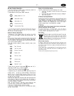
Manual Control Operation

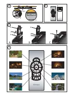
The manual controls are located on top of the appliance behind the
glass screen (see detail view ‘Y’ in

 Fig. 4

).

For description of manual button settings see below:

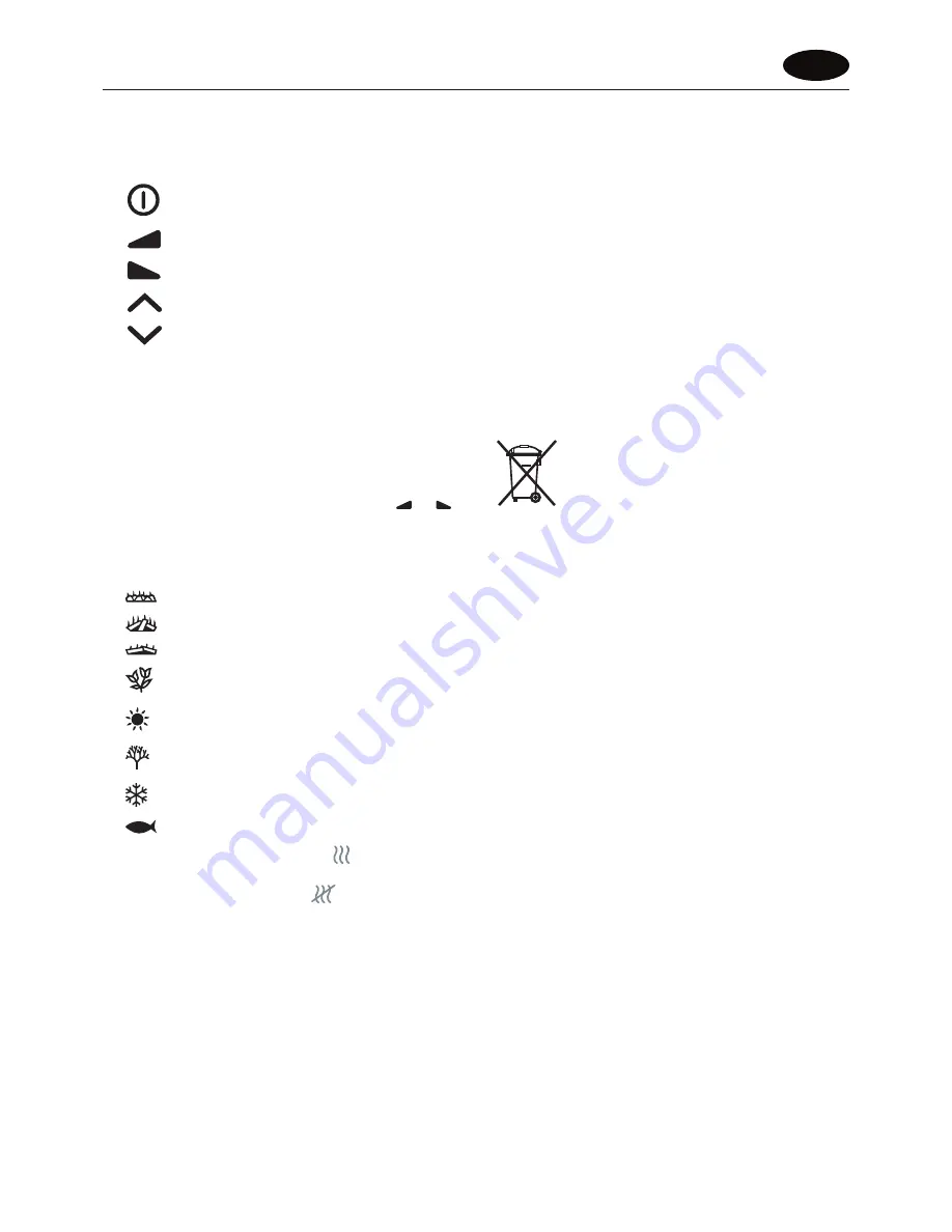
Standby Switch ‘On’

 / ‘Off’

Audio volume ‘Down’

Audio volume ‘Up’

Scene selection ‘Up’

Scene selection ‘Down’

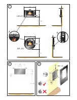
The manual Heat On/Off switch is located at the lower right side of the
appliance on Model LVA231 and at the lower left hand side of Model
LVA232 (see ‘4’ in detail B in 

Fig. 1

).

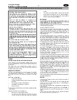
Remote Control Operation

The remote control may be operated once the appliance is switched
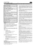
‘ON’. Select any one of eight scenes on your remote control - see

Fig. 7

.

Each scene has it’s own particular sound effect which may be activated
and adjusted by pressing the audio volume control buttons (

 and 

)

to the level required, while aiming the remote control at the IR sensors
(see ‘a’ and ‘b’ in detail A in 

Fig. 1

).

See below for button settings on remote control for various scene
selections:

‘Coal’ Fire scene

‘Log’ Fire scene

‘Embers’ Fire scene

‘Spring’ scene

‘Summer’ scene

‘Autumn’ scene

‘Winter’ scene

‘Aquarium’ scene

The heat may be switched On by pressing 

 button Heat ‘On’ is

indicated by red LED (see ‘y’ in detail A in 

Fig. 1

).

The heat may be turned Off by pressing 

 button.

The appliance may be switched into Standby mode by pressing the

Standby On/Off  

 button (see ‘x’ in detail A in 

Fig. 1

). Switching the

appliance back On using the Standby button will return to the scene
that was on the screen before turning it off. Alternatively any scene
selected may be switched on.

Note: When the appliance is switched into Standby mode the heat will
automatically be turned off, and if required when the appliance is
switched On again it must be independently switched on remotely or
manually as outlined in ‘Operation’.

Note: The user may notice a slight frame freeze lasting less than
0.5 seconds after a scene has run for approximately 5 minutes.
This is normal and should not be a cause for concern.
The user has an option of turning heat On in Standby mode without
having a scene selected.

Remote Control Assembly

Note: The remote control is packed separately in the carton.

1.

Slide open the battery cover on the back of the remote
transmitter.

2.

Install the AAA batteries into the remote control (see 

Fig. 5

).

3.

Replace battery cover.

Discard Leaking Batteries

Dispose of batteries in the proper manner according to Provincial and
local regulations. Any battery may leak electrolyte if mixed with a
different battery type, if inserted incorrectly, if all the batteries are not
replaced at the same time, if disposed of in a fire or if an attempt is
made to charge a battery not intended to be recharged

.

Cleaning

WARNING – ALWAYS DISCONNECT FROM THE POWER SUPPLY
BEFORE CLEANING THE APPLIANCE.

For general cleaning use a soft clean duster – never use abrasive
cleaners. The glass viewing screen should be cleaned carefully with a
soft cloth. DO NOT use proprietary glass cleaners.

Recycling

For electrical products sold within the European Community.

At the end of the electrical product’s useful life it should
not be disposed of with household waste. Please recycle
where facilities exist. Check with your Local Authority or
retailer for recycling advice in your country.

After Sales Service

Should you require after sales service or should you need to purchase
any spares, please contact the retailer from whom the appliance was
purchased or contact the service number relevant to your country on
the warranty card.

Please do not return a faulty product to us in the first instance as this
may result in loss or damage and delay in providing you with a
satisfactory service.

Please retain your receipt as proof of purchase.

UK

- 2 -

Summary of Contents for LVA231

Page 1: ...ES IT RU NL The product complies with the European Safety Standards EN60335 2 30 and the European Standard Electromagnetic Compatibility EMC EN55014 EN60555 2 and EN60555 3 These cover the essential requirements of EEC Directives 2006 95 EC and 2004 108 EC ...

Page 2: ...2 3 1 1 2 3 500 235 959 1209 173 209 905 65 495 750 1000 a 750 65 750 620 870 LVA 231 LVA 232 a A B x y 1 2 3 4 a b ...

Page 3: ...x y z x y z x B A C 7 5 4 6 Fig 6 X Y ...

Page 4: ......

Page 5: ...UK 1 DE 3 NL 5 FR 7 ES 9 IT 11 RU 13 ...

Page 6: ...chassis with 2 screws see detail view X in Fig 4 To wall mount the appliance first remove the wall plate from the chassis by removing the two screws and rotating the corner hinges away from the chassis Note Retain the two screws for future use Fix the wall plate to the wall using the wall plugs and screws provided Note Ensure that the wall is suitable for the screws plugs provided Use the wall pla...

Page 7: ...tlined in Operation Note The user may notice a slight frame freeze lasting less than 0 5 seconds after a scene has run for approximately 5 minutes This is normal and should not be a cause for concern The user has an option of turning heat On in Standby mode without having a scene selected Remote Control Assembly Note The remote control is packed separately in the carton 1 Slide open the battery co...

Page 8: ...bb 1 Montageort Das Gerät nicht an die Stromversorgung anschließen bevor es ordnungsgemäß an der Wand montiert ist und die Bedienungsanleitung vollständig gelesen wurde Bei der Montage des Geräts darauf achten dass in der Wand verlegte Kabel nicht beschädigt werden Vorsicht beim Bohren der Löcher Diese Modelle sind ausgelegt für ständige Wandmontage für optimale Sicht auf das Bild empfohlener Abst...

Page 9: ...andby Modus schalten siehe x in Detail A in Abb 1 Wenn das Gerät über die Standby Taste wieder eingeschaltet wird wird die Szene wieder angezeigt die beim Ausschalten auf dem Schirm angezeigt wurde Alternativ kann jede gewählte Szene eingeschaltet werden Hinweis Im Standby Modus des Geräts wird die Wärme automatisch abgeschaltet und muss wenn notwendig bei Wiedereinschalten des Geräts gesondert üb...

Page 10: ...loer en de onderzijde van het apparaat zodat u optimaal naar het scherm kunt kijken Het overzicht vanhetframeendepositievanhetstopcontactzijninfiguur 1weergegeven als stippellijnen Afmetingen die zijn aangegeven met zijn aanbevolen afmetingen Dewandplaatismet2schroevenophetframebevestigd ziedetailweergave X in figuur 4 Om het apparaat aan de muur te bevestigen verwijdert u eerst de wandplaat van h...

Page 11: ...dt de scène weergegeven die werd getoond toen het apparaat werd uitgeschakeld U kunt elke gewenste scène kiezen NB wanneer u het apparaat stand by zet wordt de verwarming automatisch uitgeschakeld en wanneer u het apparaat weer inschakelt moet u de verwarming apart activeren met of zonder de afstandsbediening zoals beschreven in Bediening NB wanneer een scène al ongeveer 5 minuten wordt afgespeeld...

Page 12: ...t d au moins 3mm dans tous les pôles L installation doit être effectuée par un électricien compétent uniquement conformément aux règlementations locales en matière de câblage Installation Ne branchez pas l appareil tant qu il n est pas correctement fixé au mur et tant que vous n avez pas lu l intégralité du mode d emploi Lors de l installation de l appareil veillez à ne pas endommager les câbles p...

Page 13: ...bouton On marche indiqué par le voyant rouge voir y dans le détail A de la Fig 1 Le chauffage peut être éteint en appuyant sur le bouton L appareil peut être mis en veille en appuyant sur le bouton veille marche arrêt voir x dans le détail A de la Fig 1 En rallumant l appareil avec le bouton veille l ambiance qui était sélectionnée auparavant réapparaîtra Autrement toute ambiance sélectionnée peut...

Page 14: ...alación distancia del suelo a la parte inferior del aparato de forma que la visualización de la pantalla sea la óptima El perfil del armazón y la posición de la toma de la red eléctrica se muestran con una línea punteada en la Fig 1 Las dimensiones marcadas con un son las medidas recomendadas La placa de la pared está sujeta al armazón por 2 tornillos vea el detalle X de la figura 4 Para montar el...

Page 15: ...o x en el detalle A de la Fig 1 Si vuelve a pulsar el botón de Standby para encender el aparato recuperará la escena que había seleccionado antes de ponerlo en reposo También puede activar cualquier escena que desee Nota Cuando el aparato se pone en modo de reposo el calor se apaga automáticamente Al volver a encender la unidad puede encenderlo manualmente por separado o con el mando a distancia c...

Page 16: ...ri Questi modelli sono stati progettati per essere montati alla parete in modo permanente Vedere Fig 1 per le distanze di fissaggio consigliate dal pavimento alla parte inferiore dell apparecchio per poter vedere al meglio il display Lo schema del telaio e la posizione della presa elettrica sono indicate con tratti punteggiati nella Fig 1 Tutte le dimensioni indicate sono consigliate La piastra de...

Page 17: ...dby premendo il tasto Standby On Off vedere x nel dettaglio A della Fig 1 Riaccendendo l apparecchiatura usando il pulsante di Standby si ritornerà alla scena attiva sullo schermo prima dello spegnimento Alternativamente si può vedere qualsiasi scena selezionata Nota Quando l apparecchio viene commutato in modalità Standby il riscaldamento si spegne automaticamente e se necessario quando si riacce...

Page 18: ... ðèñ 1 Âêë þ åíèå âûêë þ åíèå îáîãðåâà êðàñíûé ñâåòî ä è îä ñïðàâà îçíà àåòâêë þ åíèå îáîãðåâà ñì ïîçèöèþ y ñõå ì û A íà ðèñ 1 Ó ñòàíîâêà Ç à ï ð å ùàåòñ ÿ ï îäêë þ à ò ü ï ð è á î ð ï î ê à î í í å áóäåò í à ä ëåæàùèì îáðàçî ì çàêðåïëåí íà ñòåíå è èíñòðóêöèÿ ïî ýêñ ï ëóàòàöèè íå áóäåò ï îë í îñòüþ ïðî èòàíà Ó ñòàíàâëèâàéòå ïðèáîð àêêóðàòíî âî èçáåæàíèå ïîâðåæäåíèÿ êàáåëÿ ïðîëî æåííîãî â ñòåíå Ï ð...

Page 19: ...ðîìå òîãî ì îæíî âêë þ èòü ëþáîé âûáðàííûé ôîí Ï ð è ì å àíèå Êîãäà ïðèáîð ïåðåêë þ àåòñÿ â ðåæèì îæèäàíèÿ îáîãðåâ àâòî ì àòè åñêèâûêë þ àåòñÿ è ïðè íåîáõî äèìîñòè ïîñëå ï î âòî ð í î ãî âêë þ åíèÿ ïðèáîðà åãî í óæíî âêë þ àòü îòäåë ü í î ñ ïàíåëè óïðàâëåíèÿ èëè ïóëüòà äèñòàíöèîííîãî óïðàâëåíèÿ òî îïèñàíî â ðàçäåëå Ýêñïëóàòàöèÿ Ï ð è ì å àíèå Ïîñëå ïîêàçà ôîíà â òå åíèå ïðèáëèçèòåë ü í î 5 ìèíóò â...

Page 20: ... ...

Page 21: ... ...

Page 22: ... ...

Page 23: ...detaljer kan fås hos den forhandler hvor du har købt apparatet Der kan kun støttes ret på garantien ved forelæggelse af købskvittering og kun inden for garantiperioden Garantien bortfalder hvis apparatet er blevet beskadiget anvendt forkert eller i tilfælde af uautoriseret indgreb i apparatet SE Garanti För denna apparat gäller de för inköpslandet utgivna garantibestämmelserna På förfrågan kan det...

Page 24: ...ha Defeito 7 Número de Contacto e Morada NL 1 Garantiebewijs 2 Garantieperiode in jaren 3 Model len 4 Aankoopdatum 5 Stempel Ondertekening detaillist 6 Fout Defect 7 Telefoonnummer Adres DK 1 Garantikort 2 Garantiperiode i år 3 Model ler 4 Købsdato 5 Detailhandlers stempel underskrift 6 Fejl defekt 7 Kontaktnummer adresse SE 1 Garantikort 2 Garantitid i år 3 Modell er 4 Inköpsdag 5 Återförsäljaren...

Reviews: