background image

www.glendimplex.de

DOK4x HOIAO FxDEN · FD 0001

13

Air-to-water heat pump M Flex

English

6.5 Temperature sensor connection

The following temperature sensors are already installed or must
be installed additionally:

Outside temperature (R1) is (NTC-2)

Return temperature (R2) installed (NTC-10)

Demand sensor (R2.2) installed (NTC-10)

Flow rate monitoring with flow sensor (R3.1) installed
(PT1000)

Domestic hot water temperature (R3) connected (NTC-10),
still needs positioning.

6.5.1 Sensor characteristic curves

The temperature sensors to be connected to the heat pump
manager must correspond to the values specified in the table.

6.5.2 Mounting the outside temperature 

sensor

The temperature sensor must be mounted in such a way that all
weather conditions are taken into consideration and the meas-
ured value is not falsified.

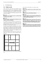
Mount on the external wall on the north or north-west side
where possible

Do not install in a "sheltered position" (e.g. in a wall niche or
under a balcony)

Not in the vicinity of windows, doors, exhaust air vents, ex-
ternal lighting or heat pumps

Not to be exposed to direct sunlight at any time of year

-

Temperature 

in °C

-20

-15

-10

-5

0

5

10

NTC-2 in k

14.6

11.4

8.9

7.1

5.6

4.5

3.7

NTC-10 in k

67.7

53.4

42.3

33.9

27.3

22.1

18.0

PT 1000 in k

0.92

0.94

0.96

0.98

1.0

1.02

1.04

15

20

25

30

35

40

45

50

55

60

2.9

2.4

2.0

1.7

1.4

1.1

1.0

0.8

0.7

0.6

14.9

12.1

10.0

8.4

7.0

5.9

5.0

4.2

3.6

3.1

1.06

1.08

1.1

1.12

1.14

1.16

1.18

1.2

1.22

1.24

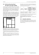
Dimensioning parameters sensor cable

Conductor material

Cu

Cable length

50 m

Ambient temperature

35 °C

Routing type

B2  (DIN  VDE  0298-4  /
IEC 60364-5-52)

External diameter

4-8 mm

Summary of Contents for M Flex Air

Page 1: ...K4x HOIAO FxDEN EN FD 0001 M Flex 0609 M Flex 0916 M Flex 0916M Installation and Operating Instruction Air to water heat pump in integral design Glen Dimplex Deutschland Dimplex 09CHOIAOF6 16IHOIAOF6...

Page 2: ......

Page 3: ...tric wire 11 6 2 Condensate drain 11 6 3 Connection on heating side 11 6 4 Domestic hot water connection 12 6 5 Temperature sensor connection 13 6 6 Electrical connection 14 6 7 Hydraulic integration...

Page 4: ...2 DOK4x HOIAO FxDEN FD 0001 www glendimplex de English Air to water heat pump M Flex 15 Information on the use of data 33 16 Declaration of conformity 34...

Page 5: ...fur ther connection requirements stipulated by local utility compa nies must also be observed When connecting the heating system all country specific reg ulations must also be adhered to This unit ca...

Page 6: ...ls the air i e ex tracts heat from it This extracted heat is then transferred to the working medium refrigerant in the evaporator The heat is pumped to a higher temperature level by increas ing its pr...

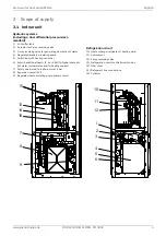
Page 7: ...ulating pump 5 Switch box with heating controller 6 Electric additional heater 2 4 or 6 kW for higher domestic hot water temperatures and for heating support 7 Safety valve start to leak pressure 2 5...

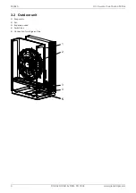
Page 8: ...6 DOK4x HOIAO FxDEN FD 0001 www glendimplex de English Air to water heat pump M Flex 3 2 Outdoor unit 1 Evaporator 2 Fan 3 Expansion valve 4 Switch box 5 Connection for refrigerant line 1 2 4 3 5 5...

Page 9: ...ed directly underneath the pallet To lift from the pallet the indoor unit can be tilted back by up to 45 and lifted by the handles on the back at the top Tilting more than 45 is not permitted Once the...

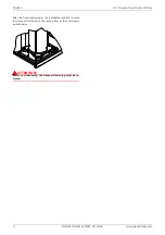
Page 10: ...nglish Air to water heat pump M Flex After the final positioning at the installation location remove the transport fastening on the sprung floor of the compressor on both sides ATTENTION Before commis...

Page 11: ...tion site Cap 12 1 on page 26 The responsibility for the heat pump installation lies with the specialist system construction company During the installation local requirements such as building regula...

Page 12: ...refrigeration lines have been connected to the indoor unit The domestic hot water sensor pre installed on the indoor unit must be inserted in the designated immersion sleeve of the cyl inder Neither...

Page 13: ...ons of the countries in question must be observed 6 3 Connection on heating side Before connecting the heating system to the heat pump the heating system must be flushed to remove any impurities resi...

Page 14: ...ed with a suitable frost protection if heat pump systems are implemented in buildings where a power failure can not be detected holiday home 6 4 Domestic hot water connection Installation and commissi...

Page 15: ...ay that all weather conditions are taken into consideration and the meas ured value is not falsified Mount on the external wall on the north or north west side where possible Do not install in a shelt...

Page 16: ...N FD 0001 www glendimplex de English Air to water heat pump M Flex 6 6 Electrical connection 6 6 1 Electrical diagram integration example Symbol legend see cap 6 6 2 on page 15 Equipment marking see c...

Page 17: ...A451 Cooling active B3 Domestic hot water thermostat B4 Swimming pool water thermostat E10 1 Electric heater E10 2 3 Oil gas boiler H5 Remote fault indicator K21 Flange heater K22 Utility block K23 Di...

Page 18: ...t be connected on plug X1 1 230V IN white on the adapter board The supply cable L N PE 230 V 50 Hz must have a continuous voltage For this reason it should be tapped upstream from the util ity company...

Page 19: ...www glendimplex de DOK4x HOIAO FxDEN FD 0001 17 Air to water heat pump M Flex English 6 7 Hydraulic integration diagram 6 7 1 Hydraulic integration diagram integration example...

Page 20: ...p M Flex 6 7 2 Symbol legend Isolating valve Safety valve combination Circulating pump Room temperature controlled valve Isolating valve with check valve Heat consumer temperature sensor Check valve T...

Page 21: ...lines must be estab lished using the brazing process All generally applicable instal lation and work steps must be followed for this The reducing sleeves provided must be used for connecting the outdo...

Page 22: ...hed An absolute pressure of at least 0 2 mbar must be achieved during evacuation Pressures below 0 2 mbar are advisable however Close the vacuum pump and start filling immediately Step 4 Filling Once...

Page 23: ...Ensure that the condensate drain functions properly The outflow from the heating water pressure relief valve must also function correctly The system must be completely filled with refrigerant and the...

Page 24: ...ned by a heating technician Based on current information we recommend using a 5 phosphoric acid solution for cleaning purposes However if cleaning needs to be performed more frequently a 5 formic acid...

Page 25: ...from the power supply HINWEIS NOTE Personal protective equipment protective goggles safety shoes and gloves where necessary must be used when work ing on the device Components with plastic parts must...

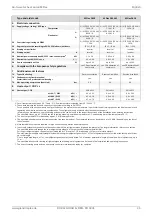
Page 26: ...e of 10 m outdoors4 Normal operation reduced operation 3 dB A 25 x 24 25 x 24 25 x 24 3 5 Sound power level in accordance with EN 12102 at A7 W55 indoors dB A 45 45 45 3 6 Sound pressure level at a di...

Page 27: ...ystem according to EN 14511 For an analysis of the economic and energy efficiency of the system other parameters in particular the defrosting capacity the bivalence point and regulation should also be...

Page 28: ...m 0 5 m 0 5 m 460 39 710 40 790 850 1231 600 206 790 538 695 995 95 174 120 55 105 40 538 39 2 3 27 110 40 205 108 160 30 30 50 710 778 372 1 1 1 7 1 2 1 3 1 4 1 8 1 5 1 6 1 1 1 2 1 3 Air intake Direc...

Page 29: ...AO FxDEN FD 0001 27 Air to water heat pump M Flex English 12 2 Dimension drawing indoor unit 2 8 2 9 2 1 2 10 2 3 2 2 2 7 2 12 2 11 600 1400 544 722 750 113 125 95 0 117 187 490 560 840 910 980 1050 1...

Page 30: ...ugh refrigerant line 18 mm 1 6 Optional feedthrough electric wires 12 mm 1 7 Optional feedthrough electric wire 1 8 External dimensions wood design variant 2 Indoor unit 2 1 Outlet overpressure 2 2 Fe...

Page 31: ...55 dB m h Emissions of nitrogen oxides NOx mg kWh Declared load profile Water heating energy efficiency wh Daily electricity consumption Qelec kWh Daily fuel consumption Qfuel kWh Contact details If C...

Page 32: ...mg kWh Declared load profile Water heating energy efficiency wh Daily electricity consumption Qelec kWh Daily fuel consumption Qfuel kWh Contact details If Cdh is not determined by measurement nthen...

Page 33: ...mg kWh Declared load profile Water heating energy efficiency wh Daily electricity consumption Qelec kWh Daily fuel consumption Qfuel kWh Contact details If Cdh is not determined by measurement nthen...

Page 34: ...ered by the warranty If it was not possible to remedy the defect the manufacturer shall either deliver a replacement free of charge or issue a reimburse ment for the reduced value In cases in which re...

Page 35: ...t en cryption methods III Use of service providers Personal data required for maintenance purposes such as your address contact details and framework data on the contract is made available to after sa...

Page 36: ...DOK4x HOIAO FxDEN FD 0001 www glendimplex de English Air to water heat pump M Flex 16 Declaration of conformity You can find and download the current CE conformity declaration at https glendimplex de...

Page 37: ...www glendimplex de DOK4x HOIAO FxDEN FD 0001 35 Air to water heat pump M Flex English...

Page 38: ...36 DOK4x HOIAO FxDEN FD 0001 www glendimplex de English Air to water heat pump M Flex...

Page 39: ...www glendimplex de DOK4x HOIAO FxDEN FD 0001 37 Air to water heat pump M Flex English...

Page 40: ...glendimplex de www glendimplex de Gesch ftsstelle sterreich Glen Dimplex Austria GmbH Hauptstra e 71 A 5302 Henndorf am Wallersee T 43 6214 20330 F 43 6214 203304 info dimplex at www dimplex at Offic...

Reviews: