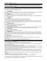
Control Knob ‘D’:- Controls the intensity of the fl ame effect.
Turning the control knob to the left increases the fl ame effect, turning the control knob to the right will
decrease
the
fl ame effect.
SETTING THE THERMOSTAT
Ensure the fi re is plugged in and switch it on to the full heat setting. Turn the Control Knob ‘C’ fully to the right (max
temperature setting) to warm the room rapidly. When the room temperature has reached the desired level, turn
the thermostat knob back slowly until you hear the thermostat just click off. The heater will then maintain the room
temperature at the chosen level.
Note: Should your heater fail to come on when the thermostat is at a low setting, this may be due to the room
temperature being higher then the thermostat setting
THERMAL SAFETY CUT-OUT
A thermal safety cut-out is incorporated in the fan heater to prevent damage due to overheating. This can happen
if the heat outlet was restricted in any way or if the chimney fl ue has not been blocked off effectively.. If the cut-out
operates, unplug the heater from the socket outlet and allow approximately 10 minutes before reconnecting. Before
switching the heater back on remove any obstruction that may be restricting the heat outlet, then continue normal
operation.
Caution:
In order to avoid a hazard due to inadvertent resetting of the thermal cutout, this appliance must not be
supplied through an external switching device, such as a timer, or connected to a switch that is regularly switched
on and off by the utility. Depending on room temperature and humidity upon initial start up there may be some
condensation on the inside of the stove. This can be overcome by turning the fl ame control knob down and leaving the
door of the stove slightly ajar, until the glass warms up.
GETTING THE DESIRED FLAME EFFECT
1. The fl ame control knob ‘D’ (Fig.10) may be turned up or down to give a more realistic effect.
2. Generally the fl ames appear more realistic when the fl ame control is turned down.
3. Give the fl ame generator time to react to changes you may make.
4. The fi re will use less water if the fl ame effect is set to a lower level.
5. Do not tilt or move the fi re while there is water in the tank or sump.
6. Make sure that the fi re is on a level fl oor.
REMOTE CONTROL OPERATION
On the control panel, Switch A (see Fig.10) must be in the ‘ON’ ( I ) position in order for the remote control to operate.
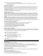
There are 3 buttons on the remote control. (See Fig.12) To operate correctly the remote must be pointed towards the
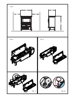
front of the grate. (See Fig 17). The remote control functions are as follows:
Press once to turn on Flame effect only.
This will be indicated by one beep.
Press once to turn on Half Heat and Flame Effect.
This will be indicated by two beeps.
Press again to turn on Full Heat and Flame Effect.
This will be indicated by three beeps.
Standby
This will be indicated by one beep.
Maintenance
GENERAL TIPS
Only use fi ltered tap water in this appliance.
Always ensure that the appliance is sitting on a level surface.
If you intend not using the appliance for longer than 2 weeks, remove and empty the sump and water tank.
Once installed, never move this appliance or lay on its back, without draining the water from sump and water tank.
The appliance should never be operated if the lamps are not working.
The lamps should be regularly inspected as described under ‘Changing lamps’.
FILLING THE WATER TANK
When the water tank is empty, the fl ame and smoke effect shuts off and you will hear 2 audible beeps, follow these
steps.
1. Press Switch ‘A’ to
(0)
(See Fig.10)
2. Gently lift out the fuelbed and carefully set aside.
3. Remove the water tank by lifting upwards and outwards.
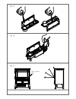
4. Place the water tank in sink and remove cap, Anti-clockwise to open. (Fig 7)


