12
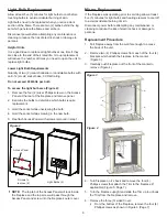
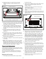
Figure 19
Phillips screws from the bottom panel as shown in
Figure 19.
Cutout Replacement
i) Using a small flat head screwdriver, backup the screw
that clamps down on the two (2) blue wires in the
Terminal Block of the Bottom Panel and release them
(Figure 19).
ii) Remove one (1) blue wire clip from the heater’s Motor
and the two (2) blue piggy-backed wire clips that lead to
the terminal on the Element (Figure 19).
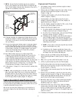
iii) From inside the chassis, remove the one (1) small
Phillips screw from the Cutout and keep it separate from
the other screws (Figure 20).
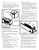
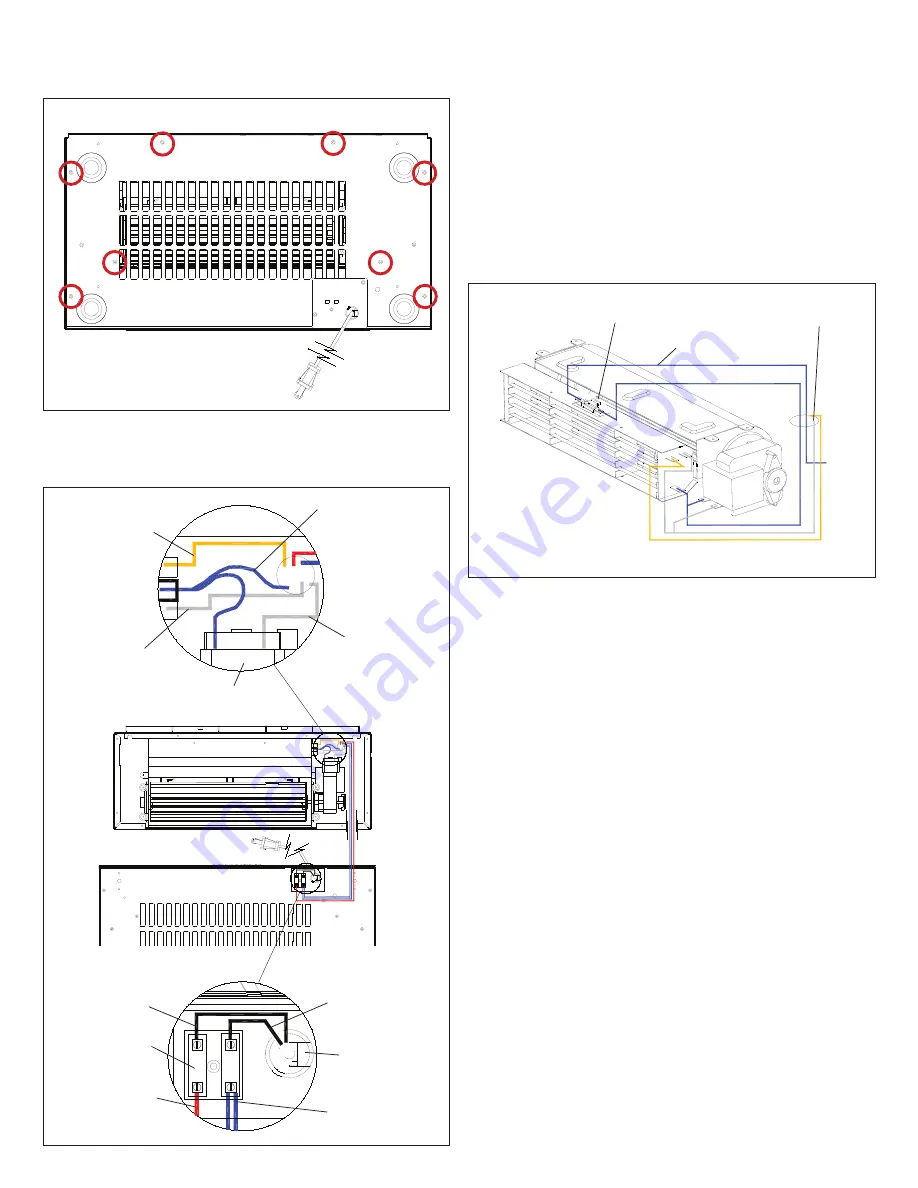
Figure 19
Screws to remove (8)
15. Use side cutters to cut all zip ties that bind wires leading
to the Terminal Block affixed to the Bottom Panel.
Yellow from
front terminal of
Element to High
Heat Switch
Blue from Cutout to
top-center terminal
of Element and
Piggy-Back to
Inside terminal of
Motor
Grey from rear
terminal of
Element to High
Heat Switch
Grey from
outside terminal
of Motor to Low
Heat Switch
1 Blue to Light
Harness, 1 Blue
to Cutout
Red from bottom
left terminal of
Terminal Block to
Main On/Off Switch
Black wire from
Power Cord with
smooth edge
Black wire from
Power Cord with
edge with ridges
Cable Clamp
Terminal Block
Motor
Element
Figure 20
Exploded view to show detail
Screw to remove (1)
To Terminal Block
Access in panel
to switches
iv) Straighten out the blue piggy-backed clips (Figure 19)
and carefully pull the Cutout and blue wires through the
sheet metal.
v) Feed the replacement Cutout wires through the same
hole in the sheet metal that the previous Cutout wires
were pulled through.
vi) Bend the Piggy-back portion of the one blue wire and
connect it to the terminal of the Element (Figure 19).
vii) Connect the last remaining blue wire clip to the Heater
Motor (Figure 19).
viii) Feed the longer blue wire from the replacement Cutout
through the hole in the sheet metal just behind the Heater
Assembly and connect it to the Terminal Block along
with the other blue wire released in step i. Use a small
flat head screwdriver to tighten down the screw in the
Terminal Block to secure wires in place.
ix) Using the small screw removed in step iii, attach the
replacement Cutout to the top of the Heater Assembly.
x) Follow steps 1 through 14 in reverse order to reassemble
the fireplace.
Heater Assembly Replacement
i) From inside the chassis, remove the one (1) small
Phillips screw from the Cutout and keep it separate from
the other screws (Figure 20).
ii) Disconnect all six (6) wire clips from the Heater
Assembly, noting their original locations (Figure 19).
Summary of Contents for Mozart CFP3811
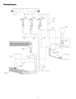
Page 5: ...5 Wiring Diagram ...

