9
carefully.
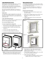
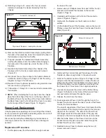
13. Depress the two (2) Retainer Clips on the top and bottom
of the switch and push the switch through the Control
Panel to remove (Figure 13).
14. Properly orientate the replacement switch and push
through the Control Panel until the Retainer Clips snap
into place.
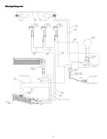
15. Re-connect the three (3) Wire Clips from step 11 (refer
to Figure 13 and wiring diagram on Page 5 for wiring
assistance).
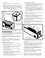
16. Re-assemble fireplace following steps 1 - 10 in reverse
order.
!
NOTE:
When installing the Cover back onto the chassis:
place the bottom flap of the Cover on the top surface of
the Bottom Panel; the rear flap of the Cover tucks behind
the Back Panel; and the front flap of the Cover to overlap
the front edge of the Chassis (Figure 10, Page 8).
Flicker Motor/Flicker Rod Replacement
If the fireplace was operating prior to servicing allow at least
five (5) minutes for light bulbs and heating element to cool off
to avoid accidental burning of skin.
Disconnect power before attempting any maintenance or
cleaning to reduce the risk of electric shock or damage to
persons.
Replacement Procedure:
1. Pull fireplace away from the wall far enough to access
the back of the unit.
2. Remove two (2) Phillips screws from each of the four (4)
brackets which attach the fireplace to the mantel
(Figure 3, Page 6).
3. Carefully push fireplace out the front of the mantel to
remove (Figure 4, Page 6).
4. Turn fireplace on it’s back and remove the four (4)
Phillips screws that attach the Trim to the fireplace (if
applicable) (Figure 5, Page 7).
5. Turn the fireplace upright and slide the Trim up to unhook
the Trim from the fireplace and remove.
6. Remove the three (3) sided Cover:
i) From the bottom of the fireplace, remove the four (4)
Phillips screws as shown in Figure 6 (Page 7).
ii) From the front of the fireplace, remove six (6) Phillips
screws as shown in Figure 7 (Page 7).
iii) Carefully turn the fireplace onto its front and remove:
two (2) Phillips screws from along the top edge of
the rear of the fireplace; and three (3) Phillips screws
from each side edge of the rear of the fireplace (8 in
total) (Figure 8, Page 7).
!
NOTE:
The number of screws along the top and side
edge of the fireplace may vary.
iv) Carefully turn the fireplace upright and remove the
three (3) sided Cover by pulling the bottom edges out
and away from the Chassis and lifting up.
7. Remove the two (2) Phillips screws that attach the
Mirror Retaining Bracket in place (Figure 9, Page 7) and
remove.
8. Slide mirror up from within the fireplace to remove.
9. Lift the Log Set straight up and out of the fireplace.
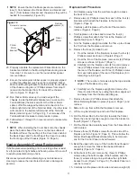
10. Pull the Flicker Rod to the far right, towards the Flicker
Motor, then bend it gently enough to clear the bracket on
the left (Figure 11, Page 8).
11. Pull the Flicker Rod carefully away from the Flicker Motor
until cleared.
!
NOTE:
If the Flicker Rod is the only item to be
replaced, install replacement Flicker Rod now and re-
assemble fireplace following steps 1 through 7 as above.
Otherwise, continue to step 12.
Figure 13
Exploded view used to show wiring detail
Access to Heater
Assembly
Casing leading to
Light Harness
A
B
C
A - Main On/Off Switch
B - Low Heat Switch
C - High Heat Switch
Retainer Clip
Figure 12
Screws to remove
(3) per side
Flicker
Rod
Flicker Rod Support
Bracket Assembly
Summary of Contents for Mozart CFP3811
Page 5: ...5 Wiring Diagram ...

