background image

WARNING – THIS APPLIANCE MUST BE EARTHED


The electrical installation must be carried out by a competent electrician, and be in strict 

accordance with the current I.E.E. Regulations for Electrical Equipment in Buildings. The 

wires in this mains lead are coloured in accordance with the following code:

GREEN AND YELLOW:


EARTH

BLUE:


NEUTRAL

BROWN

LIVE

BLACK


PILOT WIRE

- see also ‘Pilot Wire Connection’.

The heater is fitted with a length of flexible cable type H05VV-F size 4 x 1.0mm

2

 for 

connection to the fixed wiring of the premises through a suitable connection box 

positioned adjacent to the heater.

A means for disconnection must be incorporated in the fixed wiring of the premises in 

accordance with the wiring rules. The supply circuit to the heater must incorporate a 

double pole isolating switch having a contact separation of at least 3mm.

Pilot Wire Connection

The BLACK control wire is designed to carry a signal from a wall mounted Dimplex 

programmer. If a programmer is not being used, the pilot wire should be isolated in 

accordance with the current IEE Wiring Regulations.

IMPORTANT  -  DO  NOT


connect the BLACK pilot wire to earth. Care should be taken 

with the installation of the pilot wire(s) as when switching to background (setback) they 

become energised at 240V although only at a current of less than 100mA. In every case 

a suitable means of isolation must be provided for the pilot wire and marked to indicate 

that two sources of supply may be present at the heater. Where pilot wires are installed 

separately from the heater final sub-circuit they should be protected, double insulated 

and carry their own integral earth continuity conductor.

Supplementary Earth Bonding

Should Equipotential Earth Bonding be required the earthing conductor in the supply 

cord is deemed to provide the supplementary bonding connection (see Regulation 

544.2.5, 17th Edition I.E.E. Wiring Regulations).

Please  note  that  lit  cigarettes,  candles  and  oil  burners,  combined  with  the 

convection effect of electric heaters can cause soot deposits to build up on the 

surface directly above and to the sides of the heater. This is not a fault of the 

heater. Extensive burning of candles or smoking in the operating environment of 

this product can produce heavy discolouration within a few months of use.

3

Summary of Contents for QRAD050

Page 1: ...ould be read carefully and retained for future use Note also the information presented on the appliance Q Rad Electric Radiator Models QRAD050 QRAD075 QRAD100 QRAD150 QRAD200 OPERATING INSTRUCTIONS MANUAL INDEUKE3RG ISSUE 2 ...

Page 2: ...where children and vulnerable people are present Thisappliancecanbeusedbychildrenagedfrom8yearsandaboveandbypersonswith reduced physical sensory or mental capabilities or lack of experience and knowledge if they have been given supervision or instruction concerning use of the appliance in a safe way and understand the hazards involved Children shall not play with the appliance Cleaning and user ma...

Page 3: ...with the current IEE Wiring Regulations IMPORTANT DO NOT connect the BLACK pilot wire to earth Care should be taken with the installation of the pilot wire s as when switching to background setback they become energised at 240V although only at a current of less than 100mA In every case a suitable means of isolation must be provided for the pilot wire and marked to indicate that two sources of sup...

Page 4: ...100 1 0 kW 675 QRAD150 1 5 kW 756 QRAD200 2 0 kW 918 Wall Mounting IMPORTANT The wall bracket supplied with the appliance must be used The heater should be positioned observing the minimum clearances stated around the heater see Fig 1 and Fig 2 DO NOT locate the heater immediately below a fixed socket outlet or connection box 1 Remove wall mounting bracket from the back of the heater by depressing...

Page 5: ...Fig 1 Fig 3 150 mm Min 150 mm Min 546 mm A 105 mm Shelf 300 mm Model s A mm QRAD050 225 QRAD075 225 QRAD100 387 QRAD150 468 QRAD200 630 260 mm Min A 275 mm Fig 2 294 mm Min 5 ...

Page 6: ...4 00 Comms Standalone RF Module Pilot Wire Select Comfort SP 21 C For your safety this appliance is fitted with a thermal cut out In the event that the product overheats for some reason the cut out prevents excessive temperatures on the product by cutting the power to the heater Once the heater has cooled down it will reset automatically it will continue to cycle on and off automatically until the...

Page 7: ...t to automatically use one or both of these heat sources to maintain an incredibly accurate room temperature It will reduce its output as the room gets close to the target temperature too minimising the risk that the room overheats saving you energy Open window technology Should a window or door be accidentally left open your heater will detect the sudden change in temperature and go into standby ...

Page 8: ...ature set point This is the temperature that the heater will maintain during heating periods If the room temperature is above this temperature then the heater will not operate The heater leaves the factory with this temperature set at 21 C which represents a typical comfortable room temperature If you require a different room temperature then press either or on the home screen until the display sh...

Page 9: ...is timer option Preview View the times currently set Modify Change the times currently set Please refer to the operating section of this manual for information on how to modify the programmed times Advance Sometimes you may be at home when you had not planned to be or need to leave when you had planned to have the heating on You can change the way you use your heating temporarily this temporary ch...

Page 10: ...emperature is set to 26 C by default however this can be increased to 32 C if required A temperature of 21 C represents a normal room temperature The controls are located on the top right of the heater The heater is fitted with an adjustable electronic controller consisting of a display screen and six touch sensitive buttons NOTE Should the heater fail to operate this may be due to the room temper...

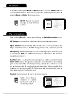
Page 11: ...s used within the menu options to confirm settings On the main screen pressing Enter will display the enabled features 6 The timed periods during which the heater is providing heat are defined as Comfort On this is displayed at the bottom of the screen Outside of heating periods the heater will not deliver heat and these periods are called Comfort Off While constant heat modes are active the mode ...

Page 12: ...ction The time clock has a battery backup that will keep the clock running in the event of a mains power outage Toadjustthetimeordatefollowthestepsbelow Press the Menu button Select Date Time by pressing the Enter button Press and to select the correct day of the month and press Enter to select Repeat this operation until the date and time has been set ensuring to press Enter to select Press Back ...

Page 13: ...table temperature of 21 C 2 Eco mode maintains a room temperature of 18 C By reducing the room temperature slightly significant energy savings can be achieved The green display colour indicates that selected temperature provides a comfortable room temperature while reducing energy consumption 3 Frost Protect mode maintains a room temperature of 7 C This mode should be used to provide protection ag...

Page 14: ...owing period When a day is complete select Save to update it Once the first day has been set up it is possible to copy these settings to successive days or all days by either choosing Copy Next or Copy All If preferred each day can be modified individually and saved It is also possible to Clear each day or Clear All days Options are Save save times for one day Copy Next copy times to following day...

Page 15: ...f days that the room will be unoccupied can be adjusted together with the required room temperature Press and to choose a holiday period between 1 and 300 days then press the Enter button Morning ON 07 00 OFF 08 30 21 C Next Out All Day Select Preview Modify TUE Holiday Active Days 07 Temperature 10 C Out All Day Selected Constant Heat Modes To choose a constant heat mode press Menu and to select ...

Page 16: ...nfo Temp Units The Options menu allows the settings to be modified to suit the user s preferences These are DST Rule Selectyourdaylightsavingsetting Theheaterclockwillautomaticallyadjust for daylight saving or British Summer Time as it is often referred to If no adjustment is required then select none Auto Lock Enable or disable the Auto Lock feature This feature locks the interface if left inacti...

Page 17: ...nal accessory is required for this function Available summer 2015 EcoStart ES to achieve the desired temperature at the onset of the timed Comfort On period the appliance anticipates when it needs to start heating prior to the onset of the timed on period E g room is 16 C with 21 C at 7am set on the timer With ES on the control will start to heat the room before 7am reaching 21 C at this time With...

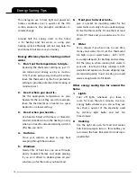
Page 18: ...s at dusk to stop heat escaping through the windows 5 Windows Nearly 25 of heat loss can occur through poorly insulated frames and single glazing If you can t afford to double glaze all your windows go for the rooms you heat most 6 Treat your hot water tank give it a jacket An insulating jacket for hot water tanks costs only a few pounds and pays for itself within months Fit one that s at least 75...

Page 19: ...is product appears damaged when first received or does not function correctly contact us by e mail at aftersales dimplex co uk or call 0844 879 3588 For ROI please call 01 842 8222 Do not return the product in the first instance as this may delay us providing you with a satisfactory service ACCIDENTAL DAMAGE IS NOT COVERED UNDER THE WARRANTY Your product is guaranteed for two years from the date o...

Page 20: ...60555 2 and EN60555 3 These cover the essential requirements of EEC Directives 2006 95 EC and 2004 108 EC GDC Group LTD All rights reserved Material contained in this publication may not be reproduced in whole or in part without prior permission in writing A division of the GDC Group LTD Millbrook house Grange Drive Hedge End Southampton SO30 2DF Millbrook House Grange Drive Hedge End Southampton ...

Reviews: