GETTING THE DESIRED FLAME EFFECT
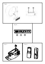
1. The flame control knob ‘C’ (Fig.10) may be turned up or down to give a more realistic effect.
2. Generally the flames appear more realistic when the flame control is turned down.
3. Give the flame generator time to react to changes you may make.
4. The appliance will use less water if the flame effect is set to a lower level (control knob ‘C’).
5. Do not tilt or move the appliance while there is water in the tank or sump.
6. Make sure that the appliance is on a level floor.
REMOTE CONTROL OPERATION
On the control panel, Switch A (see Fig.10) must be in the ‘ON’ ( I ) position in order for the remote control to operate.
There are 3 buttons on the remote control. (See Fig.12) To operate correctly the remote must be pointed towards the
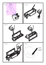
front of the grate. (See Fig 17). The remote control functions are as follows:
I
Press once to turn on Flame effect.
This will be indicated by one beep.
Standby
This will be indicated by one beep.
Maintenance
GENERAL TIPS
Only use filtered tap water in this appliance.
Always ensure that the appliance is sitting on a level surface.
If you intend not using the appliance for longer than 2 weeks, remove and empty the sump and water tank.
Once installed, never move this appliance or lay on its back, without draining the water from sump and water tank.
The appliance should never be operated if the lamps are not working.
The lamps should be regularly inspected as described under ‘Changing lamps’.
FILLING THE WATER TANK
When the water tank is empty, the flame and smoke effect shuts off and you will hear 2 audible beeps, follow these
steps.
1. Press Switch ‘A’ to
(0)
(See Fig.10)
2. Gently lift out the fuelbed and carefully set aside.
3. Remove the water tank by lifting upwards and outwards.
4. Place the water tank in sink and remove cap, Anti-clockwise to open. (Fig 7)
5. Fill tank with
filtered tap water only
. This is necessary to prolong the life of the flame and smoke producing unit.
The water should be filtered through a conventional domestic water filter unit and the filter should be replaced
regularly.
6. Screw the cap back on, do not over tighten.
7. Return the tank to the sump, with the tank cap facing down and the flat side of the tank facing outward. (Fig 8)
8. Gently place the fuelbed back into position. (Fig 9)
9. Press Switch ‘A’ to ‘ON’
(I)
position (See Fig.10)
CHANGING LAMPS
If the flame and smoke effect appears grey or colourless it may be that one or more lamps have failed.
You can check for lamp failure as follows.
1. Leaving the flame effect on, lift out the fuelbed and water tank.
2. It should be possible to view the lamps with the nozzle in place and observe which one needs to be changed.
3. Put Switch ‘A’ in the ‘OFF’ (
0
) position, and unplug the fire from the mains.
4. Leave the appliance for 20 minutes to allow the lamps to cool down before removing them.
5. Remove the sump as described in the Cleaning Section.
6. Remove the defective lamp, by gently lifting vertically and disengaging the pins from the lamp holder,
(See Fig.4 and 4a).
Replace with a Dimplex OPTIMYST, 12V, 45W, Gu5.3 base, 8º beam angle, coloured lamp. (To purchase replacement
lamps go to the section ‘After Sales Service’, details of how to purchacs the lamps are contained therein.)
7. Carefully insert the two pins of the new lamp into the two holes in the lamp holder. Push firmly in place.
(See Fig.4 and 4a).
8. Replace the sump, nozzle, water tank and fuelbed.
CLEANING
Warning
– Always press Switch ‘A’ to the ‘OFF’
(0)
position (See Fig.10) and disconnect from the power supply before
cleaning the fire.
Summary of Contents for RND020
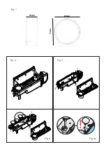
Page 2: ...Fig 1 Fig 4 Fig 4a Fig 2 Fig 3 650mm 288mm 700mm...
Page 3: ...Fig 5 Fig 5a Fig 5b Fig 6 Fig 7 Fig 8...
Page 4: ...Fig 9 Fig 10 Fig 11 Fig 12 2 3...
Page 5: ...REMOTE CONTROL SENSOR Fig 15 Fig 16 Fig 17 Fig 13 Fig 14...
Page 12: ......
Page 13: ......


