Installation Instructions
This section describes how to set up your fi re.
Before installing this appliance in an existing chimney, we recommend that;
1. You have your chimney cleaned by a competent chimney sweep.
2. You block off the chimney fl ue.
This procedure is important for the effi cient operation of the heating unit and will also reduce heat loss up the chimney.
BEFORE YOU START
1. Ensure that all packing items are removed (read any warning labels carefully) and retain all packing for possible
future use e.g. in the event of moving house or returning the appliance to your supplier.
2. Before connecting the stove, check that the supply voltage is the same as that stated on the heater.
INSTALLATION
Place the stove against a wall and connect the stove to your electricity supply.
Connect the power cable to the appropriate power connector at the back of the fi re
Plug the power cable into a 13amp/240volt outlet. Do not yet switch the appliance on.
Connecting the Transducer Unit + Lamps
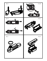
1. Release the two red tabs by turning them by 90 degrees (see Fig 2)
2. Lift out the Sump Nozzle (Fig 3)
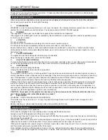
3. Insert lamps into lamp holders (Fig 4), carefully locating the pins into the holes (Fig 4a)
4. Push lamps fi rmly into place
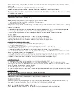
5. Place the Transducer Unit into the sump and join the cable to the connector on the sump (Fig 5)
6. To ensure that the Transducer Unit is correctly placed in the sump, the tab on the Transducer Unit should be lined
up with the moulded recess in the sump (Fig 5a).
7. Ensure that the cable is not placed above the disc on the Transducer Unit (Fig 5b). To prevent the cable becoming
pinched between the nozzle and the sump, place the cable in the slot in the wall of the sump.
8. Replace the Sump Nozzle and secure it by turning the two red tabs by 90 degrees (Fig 6)
Filling the Water Tank
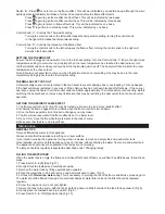
9. Place Water Tank in sink and remove cap (turn anti-clockwise to open) (Fig 7)
10. Fill Water Tank with
fi ltered tap water only
. This is necessary to prolong the life of the fl ame and smoke
producing unit. The water should be fi ltered through a conventional domestic water fi lter unit and the fi lter should be
replaced regularly. Distilled water must
not
be used.
11. Screw the cap back on –
do not overtighten
.
12. Place the Water Tank in the Sump, with the tank cap facing down and the fl at side of the tank facing outward (Fig 8)
Assembling the fi re
13. Place the Fuelbed on top of the Water Tank and Mist Nozzle (Fig 9)
Operating the Fire
This section describes how to activate your fi re using either the manual controls
MANUAL CONTROLS
The manual controls are located beneath the hinged fl ap underneath the fuelbed. Lift off the fuelbed and carefully
place aside. To access the controls lift up the fl ap. (See Fig.10 for Manual Control lay out)
Switch ‘A’:- Controls the electricity supply to the Fire.
Note: This switch must be in the ‘ON’ (
I
) position for the Fire to operate either with or without heat.
The water tank, sump, sump lid, tank cap and air fi lters must be cleaned once every two weeks, particularly in hard
water areas.
The appliance should never be operated if the lamps are not working.
The lamps should be regularly inspected as described under ‘Maintenance’ and ‘Changing lamps’.
The sump and the water tank in this product are treated with a biocidal product, Silver Biocide. This conforms with the
latest relevant ISO standard

