EN-4
452114.66.73 · FD 9306
Smart-RTC
English
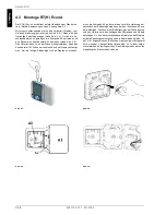
4.3 RT(H) Econ A installation
The RT(H) Econ A is mounted directly onto the wall surface.
(Device dimensions see Appendix chapter 2.2 .)
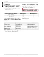
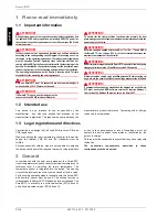
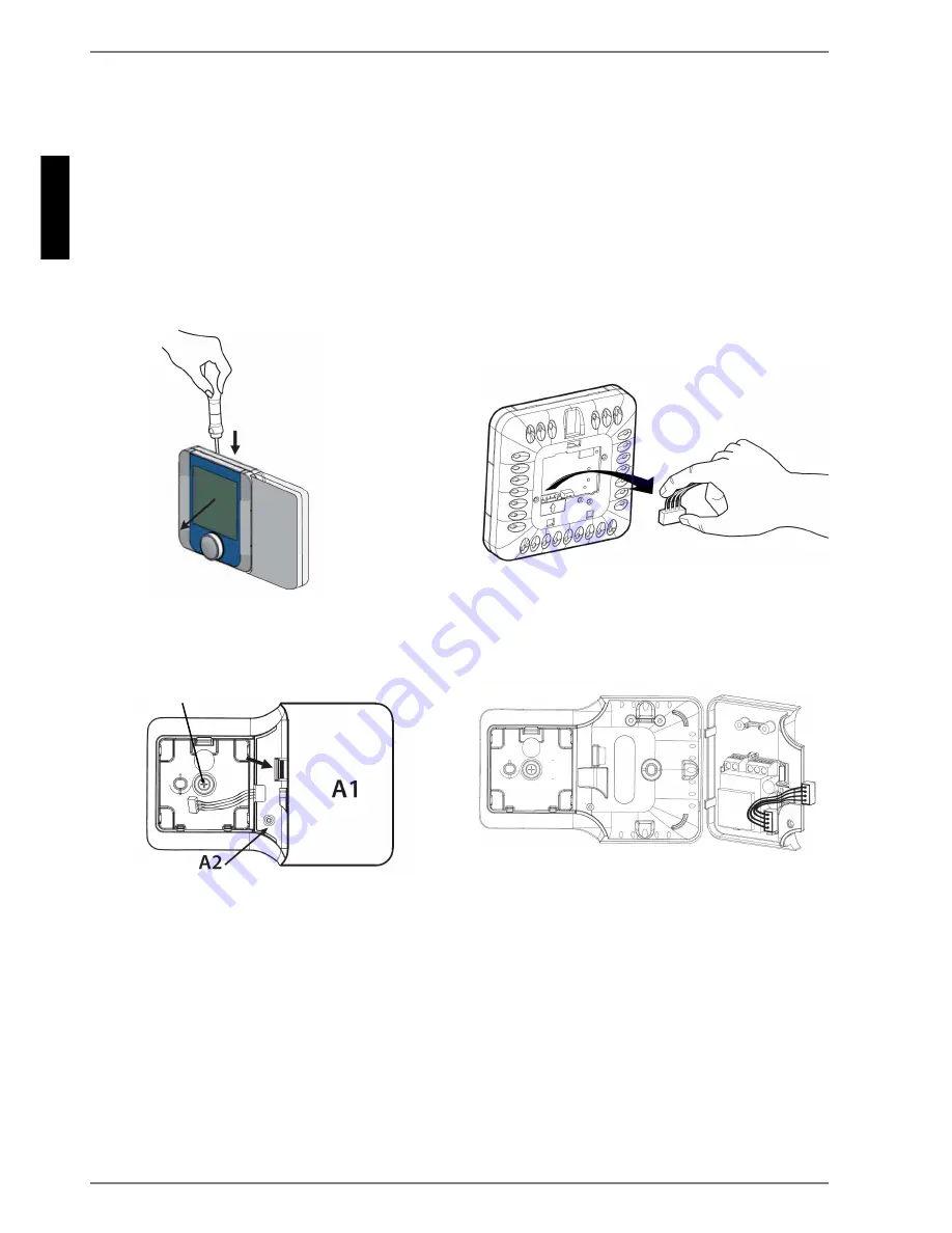
Separate the front part (display) from the rear part (mounting)
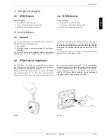
with a screwdriver (see Fig. 4.3:). Then disconnect the four-pole
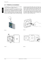
cable (see Fig. 4.4:). To access the terminals, remove screw A2
and the cover of connecting piece A1 (see Fig. 4.5:). The bottom
part can be mounted onto the wall in such a way that connecting
piece A1 is either located to the left or to the right of the display.
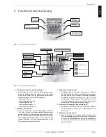
Screw A3 must be loosened in order for the correct mounting
position for the display to be obtained. After loosening the scerw,
rotate the mounting into the correct position, and re-mount with
screw A3. Drill the mounting holes into the wall and mount the
bottom part using the enclosed screws and dowels. Connect the
voltage supply and the bus connection (see chapter 4.4 on page
E-5 ) to the corresponding terminals of the controller. Before
mounting the display, re-connect the 4-pole connector (see Fig.
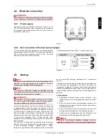
4.4:) (reverse polarity protected). Hook in the display at the
bottom, and let it snap into place at the top.
Fig. 4.3:
Fig. 4.4:
Fig. 4.5:
Fig. 4.6:
A3
Summary of Contents for RT Econ A
Page 2: ......
Page 10: ...DE 8 452114 66 73 FD 9306 Deutsch Smart RTC...
Page 18: ...EN 8 452114 66 73 FD 9306 Smart RTC English...
Page 26: ...FR 8 452114 66 73 FD 9306 Smart RTC Fran ais...
Page 30: ...A IV 452114 66 73 FD 9306 Anhang Appendix Annexes Smart RTC...
Page 31: ...452114 66 73 FD 9306 A V Anhang Appendix Annexes Smart RTC...


