www.dimplex.de/en 453322.66.16 · 10/14/B
EN-5
E
n
g
li
s
h
RTV 101EO, RTF 101EO
1.
Information for the user
ATTENTION!
The installation and assembly of electrical equip-
ment may only be performed by a skilled electri-
cian!
ATTENTION!
The modules must not be used in any relation with
equipment that supports, directly or indirectly,
human health or life or with applications that can
result in danger for people, animals or real value.
2.
Application
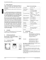
The room sensor is designed for temperature detection
or local set point adjustment with single room controls
in buildings. The sensor transmits its measuring values
battery-less to the corresponding receivers (SRC-x)
which are processing the information respectively plac-
ing the same to the disposal of a centralized control
unit, depending on the type of receiver.
In addition to the integrated temperature sensor, the
sensor has, depending on the device, a rotary button
for set point adjustment respectively a slide switch with
two switching steps.
By means of different intermediate frames, the room
sensor insert can be integrated in many switch pro-
grams of the indoor installation range. Additionally, it
can be combined with multi frames of the EnOcean
switch series “Easyfit”.
Compatible to the following designs with 55mm x
55mm inserts:
PEHA Aura
BERKER S1, B1, B3, B7 Glas
GIRA
Standard55, E2, Event, Esprit
JUNG A500, Aplus
MERTEN M-Smart, M-Arc, M-Plan.
3.
Selection of Mounting Place
For a correct and sufficient ambient brightness certain
basic conditions must be met when selecting the
mounting place.
By means of the energy-optimized EnOcean radio
technology used in our ”EasySens“ wireless sensors,
supplying themselves with electric energy by a 2 cm²
solar cell, the devices can work without batteries.
Thanks to the cessation of changeable batteries the
sensors are almost maintenance-free and environmen-
tally sound.
If necessary, the solar-powered energy storage must
be recharged after a longer storage of the wireless sen-
sors in darkness, e.g. during installation. In principle,
however, this is made automatically during the first op-
erating hours in daylight. If the initial charging should
not be sufficient in the first operating hours, the sensor
is reaching its full operating state after 3 to 4 days at
the latest. The sensor is sending properly in darkness
(in the night) after this period of time at the very latest.
When selecting the mounting place for the wireless
sensors, the following should be considered:
The minimum illumination of 200lx should be guar-
anteed at the mounting place for at least 3 or 4
hours everyday regardless whether there is artifi-
cial light or daylight.The health and safety at work
act requires a minimum illumination of 500lx for of-
fice workplaces.
A recess that is not illuminated sufficiently in the
course of a day should be avoided.
When using collimated artificial light the angle of in-
cidence on the solar cell should be not too steep.
The sensors should preferably be mounted with the
solar cell in window direction, whereas a direct sun
radiation should be avoided. An occassionally di-
rect sun radiation would lead to falsified measuring
values with the temperature detection.
With regard to a future use of the room, the mount-
ing place should be selected in that way, that a later
shadowing by the user, e.g. by filing places or roll-
ing containers, is avoided.
3.1 What to do if the ambient brightness is not
sufficient?
Depending on the application (dark rooms etc.) it is
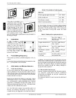
also possible to operate the device by a battery. Thus,
the sensor is equipped by a corresponding battery
holder. Battery to be used: Lithium battery 3V Type
CR2032, operating time approx. 5 to 10 years, depend-
ing on the intentional component aging and the self-
discharge of the battery used. For open the housing
yuo required a screwdriver Torx TX6. In order to
change over the sensor from solar to battery operation,
just put the coin cell into the battery holder.
4.
Mounting Advice
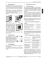
Installation is made by gluing the sensor base plate (A)
to the smooth wall surface by means of the adhesive
tape included. If required, the base plate can also be
fixed by means of rawl plugs and screws.
Afterwards, the respective switch program frame is put
on the base plate along with the intermediate frame B
(accessory). Finally, the sensor is put in the frame
center.
+
1.Release the screws 2.open bottom 3.Put coin cell into the
battery holder


