background image

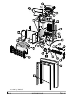
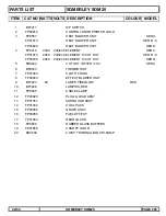
PARTS LIST

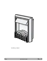
SOMERLEY SOM20

ITEM CAT 

NO WATTSVOLTS  DESCRIPTION

COLOUR MODEL

1

BF7211

S/P SWITCH

2

FP00012

CONTROL KNOB PRINTED GOLD

3

FP9557

HEAT BLOWER UNIT

SER A

FP01072

HEAT BLOWER UNIT

SER B - C

FP03029

HEAT BLOWER UNIT

SER D

4

FP9410

2000

230/240 ELEMENT

SER A

FP01073

2000

230/240 ELEMENT C/ CUT OUT

SER B - C

FP03030

2000

230/240 ELEMENT C/ CUT OUT

SER D

5

FB9402

CUT OUT (OTTER V-10)

SER A

6

BF9433

THERMOSTAT

7

FP01003

CLOTH FLAGS

8

FP00003

EFFECT BLOWER UNIT

9

BF7223

60

LAMPS FIREGLOW

RED

10

BF7226

LAMPHOLDER

11

FP9005

CABLE CLAMP

12

FP20020

PLUG & LEAD ASSY

13

FP01057

SURROUND ASSY

14

FP01034

COAL PACK

15

FP00056

GRATE ASSY

16

FP00055

FUEL EFFECT 

17

FP01084

REAR GLASS

18

FP9605

RUBBER GLASS BUFFERS

19

FP01058

CANOPY HOOD

20

BU9502

2 WAY TERMINAL BLOCK 16AMP

02/04

SOMERLEY SOM20

PAGE 203

Summary of Contents for Shaftsbury SHA20

Page 1: ...01 02 SHAFTSBURY SHA20 PAGE 1 Shaftsbury SHA20...

Page 2: ...01 02 SHAFTSBURY SHA20 PAGE 2 Dimplex SHAFTSBURY 18 20 3 4 5 19 7 2 16 17 11 21 F B C Shaftsbury SHA20 1 6 D 9 10 8 13 12 14 15 A E H 22 G Y X X X...

Page 3: ...INS CABLE 2 1 Remove the grate and fuel effect as detailed in 1 1 above and lay the fire on its back on a soft surface 2 2 Release the two screws securing terminal cover box B from underneath the chas...

Page 4: ...above 5 3 Stand the fire back up and remove the four screws at position X securing the surround to the chassis and lift the surround away 5 4 Remove the two screws near the top of the rear panel and...

Page 5: ...2000 230 240 ELEMENT ASSY C W CUT OUT SER E 5 FB9402 CUT OUT SER A 6 BF9433 THERMOSTAT 7 FP01003 CLOTH FLAGS x 10 8 FP00003 BLOWER UNIT 9 BF7223 60 LAMPS RED 10 BF7226 LAMPHOLDER 11 FP9005 CABLE CLAMP...

Page 6: ...01 02 SOMERLEY SOM20 Somerley SOM20...

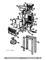
Page 7: ...01 02 SOMERLEY SOM20 Dimplex SOMERLEY 16 18 3 4 5 17 7 2 13 14 11 19 E Somerley SOM20 1 6 D 9 10 8 15 A 20 Y X X X F C 12 B...

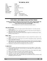
Page 8: ...uel effect assembly as detailed in 1 1 above and lay the fire on its back on a soft surface 2 2 Release the two screws securing terminal cover box B from underneath the chassis and lift the box away w...

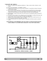
Page 9: ...can now be positioined in front of the chassis to the extent of the connecting leads 5 5 Canopy hood 21 is secured by pop rivets Drill out the rivets and on reassembly replace with rivets size M3 2 6...

Page 10: ...OUT SER B C FP03030 2000 230 240 ELEMENT C CUT OUT SER D 5 FB9402 CUT OUT OTTER V 10 SER A 6 BF9433 THERMOSTAT 7 FP01003 CLOTH FLAGS 8 FP00003 EFFECT BLOWER UNIT 9 BF7223 60 LAMPS FIREGLOW RED 10 BF7...

Reviews: