01/02
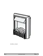
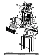
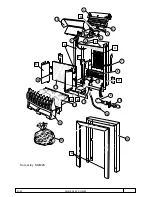
SHAFTSBURY SHA20
PAGE 4
L
E
N
60W
LAMP
60W
LAMP
ROT
ALINK
10 RPM
CUT-OUT
I
II
O
1
2
3
1
HEAT
FAN
1KW
I
II
1KW
2
3
M
EFFECT
FA
N
REAR FLAME EFFECT
4.1 Remove the grate and fuel effect and terminal cover box "B" as detailed in 2.1 and 2.2 above.
4.2 Remove glass retaining panels "F", each secured by two screws inside and one outside the chassis, and
lift mirrored glass 19 clear.
4.3 Remove motor guard "G", secured by one screw from the rear and one from undermeath the chassis.
4.4 Blower unit 8 is secured by four screws, from the underside of the chassis.
4.5 Connections are by push-on terminals. Note positions before disassembling.
4.6 Cloth flags hook onto supports at top and bottom. Ensure all flags hang freely.
4.7 Reassemble in reverse order, ensuring that cable ties are replaced where necessary and that no wires
are trapped by the terminal cover box.
FAN HEATER AND CONTROLS
5.1 Remove the log effect, and lay the fire on its back on a soft surface.
5.2 Remove the mirrored glass, as detailed in 4.2 above.
5.3 Stand the fire back up and remove the four screws at position "X", securing the surround to the chassis
and lift the surround away.
5.4 Remove the two screws near the top of the rear panel and, whilst supporting the fan heater assembly,
the two screws at position "Y" in the top of the chassis securing the fan heater assembly. The heater
assembly can now be positioined in front of the chassis to the extent of the connecting leads.
5.5 Canopy hood 21 is secured by pop rivets. Drill out the rivets, and on reassembly replace with rivets size
M3.2 - 6.5mm.
5.6 Heat blower unit 3 is secured to the control panel by four screws. Element 4 is secured to the blower unit
by four screws and cut-out 5 is secured to the element by a single screw.
5.7 The switches are a push fit; compress the clips on the switch body and ease the switch 1 forward and
out. Note connections before disconnecting push-on terminals.
5.8 Thermostat 6 is secured by two screws through the control panel; pull off control knob 2 to access the
screws.
AFTER SERVICING, IT IS RECOMMENDED THAT THE PRODUCT IS TESTED FOR INSULATION AND
EARTH CONTINUITY, IN ACCORDANCE WITH RELEVANT LOCAL SAFETY REGULATIONS.
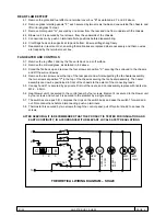
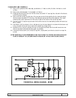
THEORETICAL WIRING DIAGRAM – SHA20

