background image

7

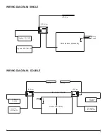
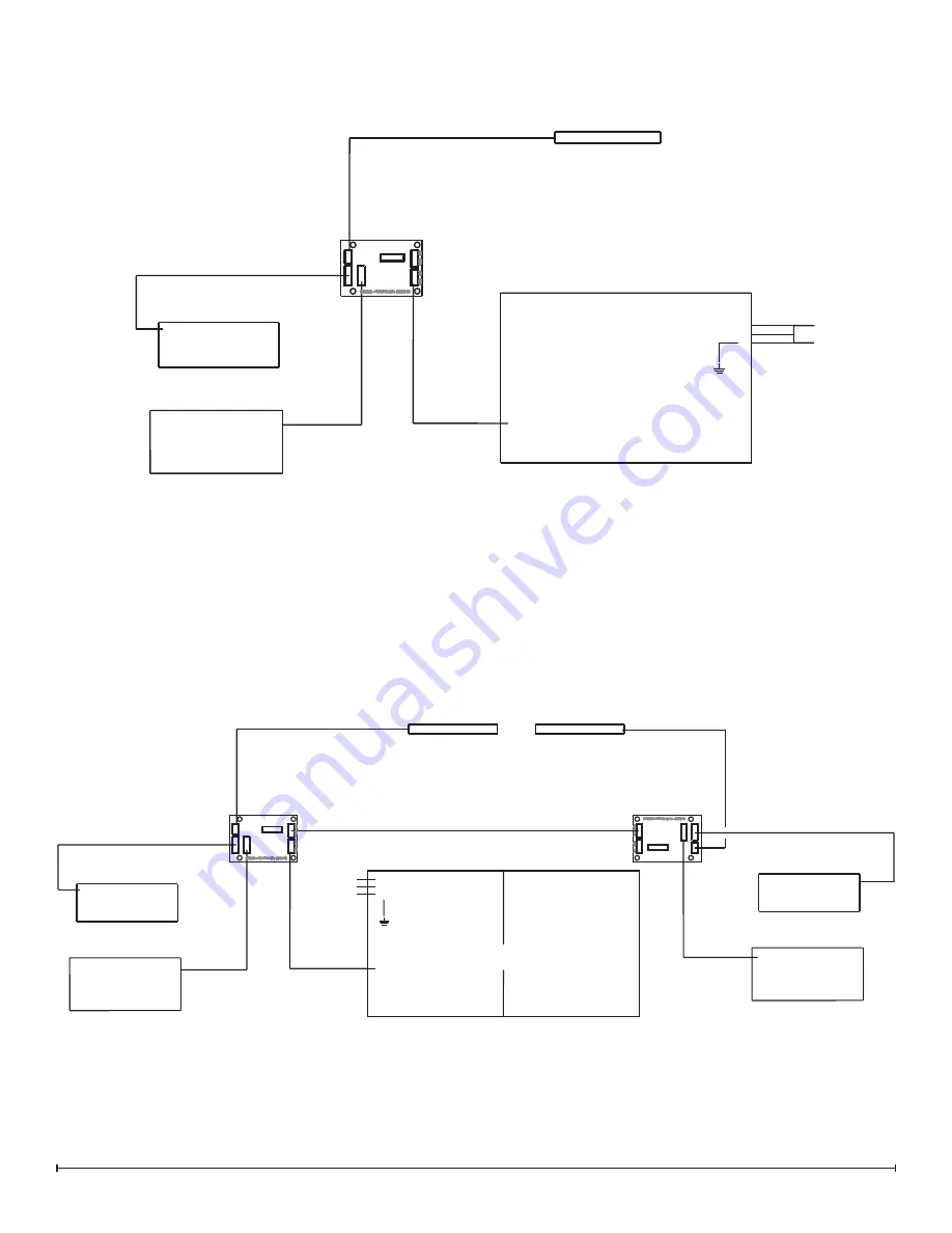
WIRING DIAGRAM- SINGLE

WIRING DIAGRAM - DOUBLE

LED Strip 

Logbed - TOP LED

Logbed - BOTTOM LED

 LED Driver

LED Screen Assembly

L

N

E

Mains

Supply

LED Strip

LH Logbed 

 TOP LED

LH Logbed 

BOTTOM LED

 LED Driver

Double LED Screen

L

N

E

Supply

Mains

LED Strip

RH Logbed 

TOP LED

RH Logbed

BOTTOM LED

 LED Driver

Power Supply Wire Harness

Summary of Contents for VF2927L

Page 1: ...plex North America Limited Dimplex North America Limited 1367 Industrial Road Cambridge ON Canada N1R 7G8 1 888 346 7539 www dimplex com REV PCN DATE 00 25 SEP 14 IMPORTANT SAFETY INFORMATION Always r...

Page 2: ...t WARNING Procedures and techniques which if not carefully followed will expose the user to the risk of fire serious injury or death OPERATION 3 MAINTENANCE 4 EXPLODED PARTS DIAGRAM SINGLE 5 EXPLODED...

Page 3: ...notice a blank screen for ap proximately 5 seconds every 30 minutes This is normal and should not be a cause for concern Manual Operation The manual controls for the screen are located at the inner to...

Page 4: ...erprints or other marks the glass can be cleaned with a dry cloth The glass should be completely dried with a lint free cloth to prevent water spots To prevent scratching do not use abrasive cleaners...

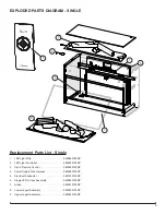
Page 5: ...880100RP 2 LED Light Controller 9600930100RP 3 Opti V Remote Control 9600950100RP 4 Power Supply Wire Harness 9600980100RP 5 Electrical Connector 9601030100RP 6 Single LED Screen Assembly 9600890100RP...

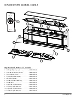
Page 6: ...nit 9600930100RP 3 Opti V Remote Control 9600950100RP 4 Power Supply Wire Harness 9600980100RP 5 Electrical Connector 9601030100RP 6 Double LED Screen Assembly 9600970100RP 7 Double Glass 9601000100RP...

Page 7: ...d TOP LED Logbed BOTTOM LED LED Driver LED Screen Assembly L N E Mains Supply LED Strip LH Logbed TOP LED LH Logbed BOTTOM LED LED Driver Double LED Screen L N E Supply Mains LED Strip RH Logbed TOP L...

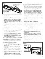
Page 8: ...crewdriver 5 16 8 mm socket wrench Suction Cups 1 Locate the glass retention strip at the top of the front glass Figure 3 2 Remove the securing screws on either side of the retention strip 3 Apply the...

Page 9: ...to the bottom of the unit 2 on either end and remove the logset NOTE The screws are recessed slightly into the em ber bed of the logset Double units Depending on which side is not working correctly re...

Page 10: ...ne on either end double units there are three two on each end and one in the middle NOTE The nuts are recessed slightly into the ember bed of the logset 10 Using a 5 16 M8 socket wrench remove the nut...

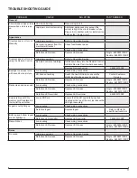
Page 11: ...ot working Switch the two SD Cards to ensure the digital input has been saved correctly Contact Customer Service Defective LED screen Replace LED screen Single 9600890100RP Double 9600970100RP Dark sc...

Reviews: