3
CAUTION: Ensure installation does not allow fire to be in direct contact with building vapor barrier
or insulation and meets all local building code.
WARNING: To reduce the risk of fire, do not store or use gasoline or other flammable vapors or
liquids in the vicinity of the heater.
1. Select a location that is not susceptible to moisture and is away from drapes, furniture and high
traffic.
2. Unpack the fire and accessories from their box.
NOTE: Leave the front glass and partially reflective glass, safely, in the box until ready for installation.
3. Store the fire in a safe, dry and dust free location until it is ready to be installed.
This electric fire is designed to be installed into a solid construction – such as an existing chimney
breast or plaster board construction. The installation of this product should be carried out by a
qualified professional.
There are several options for displaying the fire, including:
- Choice of background panel
- One, Two or Three-sided installation
- Materials to be placed onto the fuel bed
Please follow these instructions to assist you in the installation and operation of this product.
Technical Information
WARNING:
In order to avoid overheating, do not cover the appliance. Do not place material or
garments on the appliance, or obstruct the air circulation around the appliance.
The appliance carries a DO NOT COVER warning symbol.
This appliance is equipped with a device to control the room temperature. Do not use this appliance
in small rooms when they are occupied by persons not capable of leaving the room on their own,
unless constant supervision is provided
.
Thank you for choosing a Dimplex electric fire.
General Information
Dimplex Vivente Electric Fire
Models: VVT75, VVT100, VVT150
Heat Output
230V
240V
Nominal Heat Output
P
Nom
1.4
1.5
kW
Minimum Heat Output
P
min
1.3
1.4
kW
Maximum Continuous Heat Output
P
max
1.4
1.5
kW
Auxiliary Electricity Consumption
In Standby Mode
el
SB
0.49
0.49
W
with electronic room temperature control.
Summary of Contents for Vivente
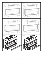
Page 14: ...14 Fig 2 Fig 3a Fig 1a Fig 1b Fig 1c Fig 1d...
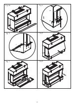
Page 15: ...15 Fig 5 Fig 7 Fig 8 Fig 4 Fig 3b Fig 6 1 2 1 2...
Page 16: ...16 Fig 10a Fig 10b Fig 9...
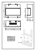
Page 18: ...18 Fig 14 Fig 13a Fig 13c Fig 13b Fig 12 150mm 200 800mm...
Page 19: ...19 Fig 17 Fig 16 A C E G I K B D F H J L Fig 15 I 0...
Page 20: ...20 VVT75...
Page 21: ...21 VVT100...
Page 22: ...22 VVT150...
Page 23: ...23 Fig 18...

