background image

4

Step 1: Choosing Installation Type

The Vivente can be configured in 4 different ways:

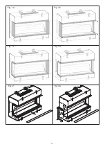
•  Single-sided – Front glass only (see Fig 1a) 

•   Two-sided Right (see Fig 1b)

•   Two-sided Left (see Fig 1c)

•   Three-sided (see Fig 1d). 

The Vivente is supplied as a Three-sided configuration.

Please follow the steps below to adjust to your desired arrangement.

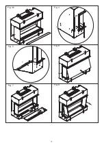
1. Remove front bottom trim on unit. See Fig. 2

2. On the desired side you wish to cover, remove side glass trim which is held in place by 

four screws. Attach side panel in place of the side trim using the same four screws See Fig. 

3a & 3b

3. For Front Glass Only setup, repeat Step 2 on the opposite side of product. 

4. Assemble the appropriate front Trim to the product. See Fig. 2

 (Three different trims are provided with the product to facilitate the various setup options.)  

Step 2: Choosing Back Panel

The Vivente comes with two back panels, offering four different finishes. 

The product is provided with one back panel in the unit. If you wish to change this to another 

back panel design, it is advised to do so before installing the product. It is possible to fit the 

back panel after the product has been installed, but it takes significantly longer and should 

only be done by a qualified professional or competinent person.

All panel finishes provided contain a decorative finish, which complements the flame effect. 

If so desired, these back panels can be painted with alternative colours.

The plain panel can also be painted or decorated with wallpaper to create a unique panel, 

please follow the instructions on your selected paint or wallpaper adhesive, for bonding on 

top of the painted MDF panel.

Please take care not to scratch these panels while storing or fitting them.

Fitting Panel – Before Installation (Recommended)

1. Remove side bracket as displayed on Fig. 4

2. The side bracket can be used to take out the back panel. Insert the bottom part of the 

side bracket into the Back Panel notch, and slide out the back panel (Fig.5).

3. Place the desired back panel into position and reassemble side bracket using two screws. 

Installation Instructions

Summary of Contents for Vivente

Page 1: ...sau utiliz rii ocazionale CZ Tento v robek je vhodn pouze do dob e izolovan ch prostor nebo k p le itostn mu pou it DK Dette produkt er kun egnet til velisolerede rum eller lejlighedsvis brug PT Este...

Page 2: ...pliance or perform user maintenance CAUTION Some parts of this product can become very hot and cause burns Particular attention has to be given where children and vulnerable people are present Do not...

Page 3: ...displaying the fire including Choice of background panel One Two or Three sided installation Materials to be placed onto the fuel bed Please follow these instructions to assist you in the installation...

Page 4: ...panel in the unit If you wish to change this to another back panel design it is advised to do so before installing the product It is possible to fit the back panel after the product has been installed...

Page 5: ...reen Step 3 Installing the Product CAUTION Two people will be required for various steps of this procedure This product is designed to be installed into existing block wall or a custom built studded w...

Page 6: ...arked The following fuel bed media is included Ceramic Logs Ash Dust Crystal pieces We have taken great care to create what we feel is the most authentic fuel bed please follow the steps below for mor...

Page 7: ...ttage to match the requirements of the room based on the thermostat setting Conventional electric heaters work by simply being fully on or off which can result in swings from slightly too warm to slig...

Page 8: ...hours of 5 11pm so if you enter the room during the day the fire will not react However in the evening your Dimplex fire will instantly switch on your flame effect remembering your last setting 24 Hr...

Page 9: ...and VOL FIRE The Flame Brightness Setting can then be adjusted using the or buttons There are seven settings Display shows F1 to F5 for the different levels of brightness F6 for Pulsating Effect and O...

Page 10: ...multiple times to lower the heater temperature in 10 C increments The lowest temperature that can be set is 150 C F 32ST Temp Up Press Once to display current Set Temperature Press multiple times to i...

Page 11: ...n CD20 Room Sensor NTC Error Contact your retailer and reference this error code CD03 The internal NTC is measuring elevated tempera tures within the product Unplug Unit at power supply to reset allow...

Page 12: ...erprints or other marks the partially reflective glass can be cleaned with a damp cloth The partially reflective glass should be completely dried with a lint free cloth to prevent water spots To preve...

Page 13: ...he mains power lead must be replaced by the manufacturer or its authorised dealer Should you require after sales information or assistance with this product please go to www dimplex co uk and select C...

Page 14: ...14 Fig 2 Fig 3a Fig 1a Fig 1b Fig 1c Fig 1d...

Page 15: ...15 Fig 5 Fig 7 Fig 8 Fig 4 Fig 3b Fig 6 1 2 1 2...

Page 16: ...16 Fig 10a Fig 10b Fig 9...

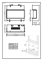
Page 17: ...17 X 310 200 800 670 Fig 11 MODEL X VVT75 764mm VVT100 1014mm VVT150 1514mm X X 30mm 321 666 350 120 172 307...

Page 18: ...18 Fig 14 Fig 13a Fig 13c Fig 13b Fig 12 150mm 200 800mm...

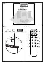
Page 19: ...19 Fig 17 Fig 16 A C E G I K B D F H J L Fig 15 I 0...

Page 20: ...20 VVT75...

Page 21: ...21 VVT100...

Page 22: ...22 VVT150...

Page 23: ...23 Fig 18...

Page 24: ...plex Millbrook House Grange Drive Hedge End Southampton SO30 2DF Glen Dimplex Heating and Ventilation All rights reserved Material contained in this publication may not be reproduced in whole or in pa...

Reviews: