5
Fitting panel – After Installation
The Back Panel can also be change after the product has been installed, a person of suitable
competentancy is required to carry out this task. Please follow the steps below.
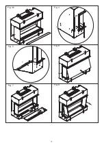
1. Disconnect product from Power Supply and remove front trim on unit. See Fig. 2
2. Remove Front Glass from product and store in a safe place. See Fig. 6 (A suction cup is
provided to help remove/replace the front glass.)
3. Remove Fuelbed fixing screws, then remove Fuelbed. (Fig. 7) It is recommeneded that the
logs are carefully removed before lifting out the fuel bed.
4. Remove both Side Glasses by tilting them in at the bottom, then sliding down and out to
remove. Store these in a safe place. (Fig. 8).
5. Remove plastic Inner Screen by tilting it from the base. (Fig.9) Use finger access provided
to allow you to contact the bottom of the screen.
6. Remove Back Inner Panel bracket (Fig. 10a), there are a number of keyhole slots which
allow for the bracket to be removed without removing the fixing screws.
Inner Back panel can then be tilted and removed from its housing. (Fig. 10b)
7. Replace with new Back Inner Panel, and reverse the steps set out above, to re-assemble
the product. Ensure Inner screen is reassembled correctly into its locating slot at the top.
(Smooth mirrored finish to face the front of the product, on the larger units an extra person
maybe required to simply the refitment of the Inner screen.)
Step 3: Installing the Product
CAUTION: Two people will be required for various steps of this procedure.
This product is designed to be installed into existing block wall or a custom-built studded
wall structure. Please consult a competent installer before undertaking this to ensure a
safe and secure installation. If installing into an existing chimney or flue, please ensure
that the chimney or flue is blocked off. This is to prevent up-draughts affecting product
operation.
Electrical Requirements
NOTE: A dedicated, properly fused 13 Amp circuit is required, rated for the appropriate
voltage (230-240V). An isolation switch should also be incorporated in cases where the
product plug is inaccessible after installation.
An access panel is provided in the base of the product, it is advisable that the plug is
located directly below this panel in the event that access is required to the plug after
installation.
WARNING: Construction and wiring must comply with local building codes and other
applicable regulations to reduce the risk of fire, electric shock and injury to persons.
WARNING: To reduce the risk of fire, electric shock or injury to persons, always use a
licensed electrician.
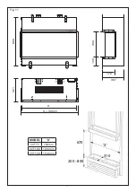
1. Using the product dimensions (Fig. 11), build a suitable structure for the product to fit
into. Ensure that, when installed, the product is within 1m of a power outlet. Please refer
to Electrical Requirements section above for more details.
It is recommended that the base of the unit is installed between 200mm and 800mm from
the floor. This is to maintain an optimised viewing angle of the fire effect. (See Fig. 12)
Summary of Contents for Vivente
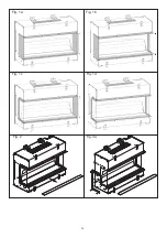
Page 14: ...14 Fig 2 Fig 3a Fig 1a Fig 1b Fig 1c Fig 1d...
Page 15: ...15 Fig 5 Fig 7 Fig 8 Fig 4 Fig 3b Fig 6 1 2 1 2...
Page 16: ...16 Fig 10a Fig 10b Fig 9...
Page 18: ...18 Fig 14 Fig 13a Fig 13c Fig 13b Fig 12 150mm 200 800mm...
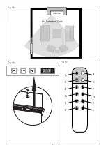
Page 19: ...19 Fig 17 Fig 16 A C E G I K B D F H J L Fig 15 I 0...
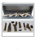
Page 20: ...20 VVT75...
Page 21: ...21 VVT100...
Page 22: ...22 VVT150...
Page 23: ...23 Fig 18...

