background image

Installation Instructions

This section describes how to set up your 

fi

 re.

BEFORE YOU START

1. Ensure that all packing items are removed (read any warning labels carefully) and retain all packing for possible 
future use e.g. in the event of moving house or returning the appliance to your supplier.
2. Before connecting to the mains supply, check that the supply voltage is the same as that stated on the appliance.

ALTERNATIVE BACK PANEL

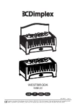
An alternative back panel is supplied (see front page).
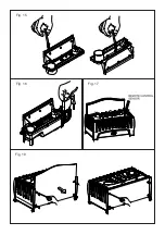
To take existing back panel off, unscrew 4 screws from the rear. Fit smaller back panel and re

fi

 x 4 screws (Fig. 18). 

INSTALLATION

Place the appliance against a wall.

Connecting the Transducer Unit + Lamps
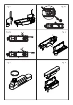
1. Release the two red tabs by turning them by 90 degrees (see Fig 2)
2. Lift out the Sump Nozzle (Fig 3)
3. Insert lamps into lamp holders (Fig 4), carefully locating the pins into the holes (Fig 4a)
4. Push lamps 

fi

 rmly into place

5. Place the Transducer Unit into the sump and join the cable to the connector on the sump (Fig 5)
6. To ensure that the Transducer Unit is correctly placed in the sump, the tab on the Transducer Unit should be lined 
up with the moulded recess in the sump (Fig 5a).
7. Ensure that the cable is not placed above the disc on the Transducer Unit (Fig 5b).  To prevent the cable becoming 
pinched between the nozzle and the sump, place the cable in the slot in the wall of the sump.
8. Replace the Sump Nozzle and secure it by turning the two red tabs by 90 degrees (Fig 6)

Filling the Water Tank
9. Place Water Tank in sink and remove cap (turn anti-clockwise to open) (Fig 7)
10. Fill Water Tank with 

fi

 ltered tap water only

. This is necessary to prolong the life of the 

fl

 ame and smoke effect 

producing unit. The water should be 

fi

 ltered through a conventional domestic water 

fi

 lter unit and the 

fi

 lter should be 

replaced regularly. Distilled water must 

not

 be used.

11. Screw the cap back on – 

do not overtighten

.

12. Place the Water Tank in the Sump, with the tank cap facing down and the 

fl

 at side of the tank facing outward (Fig 8)

Assembling the 

fi

 re

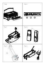
13. Place the Fuelbed on top of the Water Tank and Mist Nozzle (Fig 9)

Connect the power cable to the appropriate power connector at the back of the appliance and 
Plug the power cable into a 13amp/240volt outlet. The appliance is now ready for use.

Operating the Fire

This section describes how to activate your 

fi

 re using either the manual controls or remote control.

MANUAL CONTROLS

The manual controls are located beneath the hinged 

fl

 ap. 

(See Fig.10 for Manual Control lay out)

Switch ‘A’:- Controls the electricity supply to the Fire.
Note: This switch must be in the ‘ON’ ( 

) position for the Fire to operate.

Switch ‘B’:- Press      once to turn on the 

fl

  ame  effect.  This  will  be    indicated  by  an  audible  beep. Although  the  main              

lights operate immediately it will take a further 30 seconds before the 

fl

 ame effect starts.

Press   to put 

fi

 re in to standby mode. This will be indicated by one beep.

Control Knob ‘C’:- Controls the intensity of the 

fl

 ame effect. 

Turning the control knob to the left increases the 

fl

 ame effect, turning the control knob to the right will  


decrease the 

fl

 ame effect.

2

Summary of Contents for WBK20

Page 1: ...afety Standards EN60335 2 30 and the European Standard Electromagnetic Compatibility EMC EN55014 EN60555 2 and EN60555 3 These cover the essential requirements of EEC Directives 2006 95 EC and 2004 10...

Page 2: ...Fig 1 Fig 4 Fig 4a Fig 2 Fig 3...

Page 3: ...Fig 5 Fig 5a Fig 5b Fig 6 Fig 7 Fig 8...

Page 4: ...Fig 9 Fig 10 Fig 11 Fig 12 Fig 13 Fig 14...

Page 5: ...Fig 15 Fig 16 Fig 17 Fig 18...

Page 6: ...UK 1 IT 7 ES 13 RU 19...

Page 7: ...physical sensory or mental capabilities or lack of experience and knowledge unless they have been given supervision or instruction concerning use of the appliance by a person responsible for their saf...

Page 8: ...rees Fig 6 Filling the Water Tank 9 Place Water Tank in sink and remove cap turn anti clockwise to open Fig 7 10 Fill Water Tank with filtered tap water only This is necessary to prolong the life of t...

Page 9: ...le beeps follow these steps 1 Press Switch A to 0 See Fig 10 2 Gently lift out the fuelbed and carefully set aside 3 Remove the water tank by lifting upwards and outwards 4 Place the water tank in sin...

Page 10: ...nnect the electrical connector located on the right side of the sump See Fig 5 5 Release the right sump locking tabs by turning 90 This allows the sump to be lifted completely from its location 6 Gent...

Page 11: ...or retailer for recycling advice in your country PATENT PATENT APPLICATION Products within the Optimyst range are protected by one or more of the following patents and patent applications Great Britai...

Page 12: ...ng Control knob D to the left slowly See Fig 10 Clean the Metal Disc with soft brush supplied See Fig 14 See Maintenance for a step by step procedure Direct the wire to the back of the sump and make s...

Page 13: ...istruite sull utilizzo del prodotto o siano sottoposte alla supervisione di una persona responsabile della loro sicurezza Sorvegliare i bambini ed evitare che giochino con l unit 7 ELETTRICIT AVVERTEN...

Page 14: ...lta disporre il cavo nella fessura nella parete della vasca 8 Sostituire l ugello della vasca di raccolta e fissarlo ruotando le due alette rosse di 90 gradi Fig 6 Riempimento del serbatoio dell acqua...

Page 15: ...azione non spostare l unit e non appoggiarla sul dorso senza aver prima vuotato la vasca di raccolta e il serbatoio dell acqua L unit non deve mai essere utilizzata se le lampadine non funzionano Le l...

Page 16: ...il tappo non stringere eccessivamente Vasca di raccolta 1 Portare l interruttore A su OFF 0 2 Sollevare delicatamente il piano del combustibile e adagiarlo a terra facendo attenzione 3 Rimuovere il s...

Page 17: ...rivenditore di fiducia per avere informazioni in materia di smaltimento applicabili al proprio paese BREVETTO DOMANDA DI BREVETTO I prodotti della linea Optimyst sono tutelati da uno o pi dei seguent...

Page 18: ...vedere Fig 10 Pulire il disco di metallo con la spazzola morbida fornita in dotazione vedere Fig 14 Vedere Manutenzione per i singoli passi della procedura Indirizzare il filo verso il retro della va...

Page 19: ...des f sicas sensoriales o mentales limitadas o con falta de experiencia y conocimiento a menos que una persona responsable de su seguridad les supervise o instruya en el uso del aparato Los ni os debe...

Page 20: ...ed del sumidero 8 Sustituya la boquilla del sumidero y aseg rela girando 90 las dos leng etas rojas Fig 6 Llenado del dep sito de agua 9 Coloque el dep sito de agua en un fregadero y retire la tapa gi...

Page 21: ...de bombillas LLENADO DEL DEP SITO DE AGUA Cuando el dep sito de agua est vac o los efectos de llama y humo se detengan y escuche dos se ales ac sticas proceda como sigue 1 Coloque el interruptor A en...

Page 22: ...ado en el suelo 3 Retire el dep sito de agua levant ndolo hacia arriba 4 Desenchufe el conector el ctrico que se encuentra en la parte derecha del sumidero Consulte la Fig 5 5 Suelte las leng etas de...

Page 23: ...nsulte a las autoridades locales o a su proveedor para obtener informaci n acerca del reciclaje en su pa s PATENTE SOLICITUD DE PATENTE Los productos de la gama Optimyst est n protegidos por una o var...

Page 24: ...10 Limpie el disco met lico con el cepillo suministrado Consulte la Fig 14 Para obtener informaci n sobre el procedimiento detallado consulte la secci n Mantenimiento Dirija el cable a la parte poster...

Page 25: ...Dimplex OPTIMYST Dimplex 1 2 3 1 4 5 6 7 30 2 19...

Page 26: ...1 2 4 4 18 1 90 2 2 3 3 4 4 4 5 5 6 5a 7 5b 8 90 6 9 7 10 11 12 8 13 9 13 240 10 A I B 30 C 20...

Page 27: ...1 10 2 3 4 5 6 10 I 3 12 17 I 2 2 1 0 10 2 3 4 7 5 6 7 8 8 9 9 I 10 1 2 3 0 4 20 5 6 4 4 Dimplex OPTIMYST 12 45 Gu5 3 8 http spares dimplex co uk 7 4 4 8 21 www dimplex kaminy com ua...

Page 28: ...0 10 2 1 2 3 4 1 0 2 3 4 5 5 90 6 7 90 3 8 13 9 14 10 11 15 12 1 2 16 3 4 5 www dimplex co uk 0845 600 5111 01 842 4833 22...

Page 29: ...648 US 13 167 042 RU 2008140317 EP 2029941 EP 2201301 EP 2315976 EP 1787063 EP 07723217 1 EP 11170434 2 EP 11170435 9 CN 101883953 CN 200980128666 2 CN 101057105 CN 101438104 AU 2009248743 AU 20072246...

Page 30: ......

Page 31: ...do per odo da garantia O direito de reclama o ao abrigo da garantia expira no caso do aparelho ter sido danificado utilizado de forma incorrecta ou de se terem efectuado manipula es n o autorizadas NL...

Page 32: ...arantiperiode i r 3 Model ler 4 K bsdato 5 Detailhandlers stempel underskrift 6 Fejl defekt 7 Kontaktnummer adresse SE 1 Garantikort 2 Garantitid i r 3 Modell er 4 Ink psdag 5 terf rs ljarens st mpel...

Reviews: