background image


www.dimplex.com

Always use a qualified technician or service agency to repair this firebox.

!

 NOTE: 

 Procedures and techniques that are considered important enough to emphasize.

 CAUTION:

  Procedures and techniques which, if not carefully followed, will result in damage to the equipment.


WARNING:

  Procedures and techniques which, if not carefully followed, will expose the user to the risk of fire, serious 

injury, or death.

Operation   .  .  .  .  .  .  .  .  .  .  .  .  .  .  .  .  .  .  .  .  .  .  .  .  .  .  .  .  .  .  .  .  .  .  .  .  .  .  .  .  .  .  .  .  .  .  .  .  .  .  .  .  .  .  .  .  .  .  . 3
Exploded Parts Diagram  .  .  .  .  .  .  .  .  .  .  .  .  .  .  .  .  .  .  .  .  .  .  .  .  .  .  .  .  .  .  .  .  .  .  .  .  .  .  .  .  .  .  .  .  .  .  . 6
Replacement Parts List  .  .  .  .  .  .  .  .  .  .  .  .  .  .  .  .  .  .  .  .  .  .  .  .  .  .  .  .  .  .  .  .  .  .  .  .  .  .  .  .  .  .  .  .  .  .  .  . 6
Wiring Diagram   .  .  .  .  .  .  .  .  .  .  .  .  .  .  .  .  .  .  .  .  .  .  .  .  .  .  .  .  .  .  .  .  .  .  .  .  .  .  .  .  .  .  .  .  .  .  .  .  .  .  .  .  .  . 7
Accessing Top Components    .  .  .  .  .  .  .  .  .  .  .  .  .  .  .  .  .  .  .  .  .  .  .  .  .  .  .  .  .  .  .  .  .  .  .  .  .  .  .  .  .  .  . 8
Accessing Bottom components  .  .  .  .  .  .  .  .  .  .  .  .  .  .  .  .  .  .  .  .  .  .  .  .  .  .  .  .  .  .  .  .  .  .  .  .  .  .  .  .  . 8

Power Cord Replacement    .  .  .  .  .  .  .  .  .  .  .  .  .  .  .  .  .  .  .  .  .  .  .  .  .  .  .  .  .  .  .  .  .  .  .  .  .  .  .  .  .  .  . 9
Main Control Board Replacement   .  .  .  .  .  .  .  .  .  .  .  .  .  .  .  .  .  .  .  .  .  .  .  .  .  .  .  .  .  .  .  .  .  .  .  .  . 9
Heater Assembly Replacement   .  .  .  .  .  .  .  .  .  .  .  .  .  .  .  .  .  .  .  .  .  .  .  .  .  .  .  .  .  .  .  .  .  .  .  .  .  . 10
Touchpad Replacement   .  .  .  .  .  .  .  .  .  .  .  .  .  .  .  .  .  .  .  .  .  .  .  .  .  .  .  .  .  .  .  .  .  .  .  .  .  .  .  .  .  .  .  . 10
Flicker Motor Replacement   .  .  .  .  .  .  .  .  .  .  .  .  .  .  .  .  .  .  .  .  .  .  .  .  .  .  .  .  .  .  .  .  .  .  .  .  .  .  .  .  . 10
Flicker Rod Replacement  .  .  .  .  .  .  .  .  .  .  .  .  .  .  .  .  .  .  .  .  .  .  .  .  .  .  .  .  .  .  .  .  .  .  .  .  .  .  .  .  .  .  . 11
Flame Base LED Strip Replacement   .  .  .  .  .  .  .  .  .  .  .  .  .  .  .  .  .  .  .  .  .  .  .  .  .  .  .  .  .  .  .  .  .  . 11
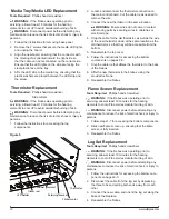
Media Tray/Media LED Replacement    .  .  .  .  .  .  .  .  .  .  .  .  .  .  .  .  .  .  .  .  .  .  .  .  .  .  .  .  .  .  .  .  . 12
Flame Screen Replacement   .  .  .  .  .  .  .  .  .  .  .  .  .  .  .  .  .  .  .  .  .  .  .  .  .  .  .  .  .  .  .  .  .  .  .  .  .  .  .  .  . 12
Log Set Replacement   .  .  .  .  .  .  .  .  .  .  .  .  .  .  .  .  .  .  .  .  .  .  .  .  .  .  .  .  .  .  .  .  .  .  .  .  .  .  .  .  .  .  .  .  .  . 12

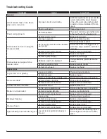
Troubleshooting Guide   .  .  .  .  .  .  .  .  .  .  .  .  .  .  .  .  .  .  .  .  .  .  .  .  .  .  .  .  .  .  .  .  .  .  .  .  .  .  .  .  .  .  .  .  .  .  . 13

Table of Contents

Summary of Contents for XHD23G

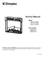
Page 1: ...XX 6909850XXX 6909970XXX 7401050100R00 IMPORTANT SAFETY INFORMATION Always read this manual first before attempting to service this firebox For your safety always comply with all warnings and safety i...

Page 2: ...owed will expose the user to the risk of fire serious injury or death Operation 3 Exploded Parts Diagram 6 Replacement Parts List 6 Wiring Diagram 7 Accessing Top Components 8 Accessing Bottom compone...

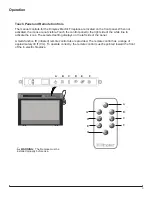
Page 3: ...control panel to the right side of the white line to activate the icons The selected setting displays on the left side of the panel A multi function IR infrared remote control also is provided The rem...

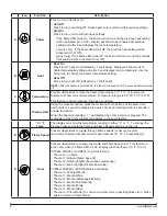
Page 4: ...nge is 62o 78o F 17o 26o C This feature is active whenever the heat is enabled Disable Heat Using the manual controls press the Heat and Temp buttons at the same time and hold for 2 second to disable...

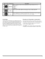
Page 5: ...lay will show b3 b1 b2 respectively High Low Medium G Flame Press to turn the flame effect On Press again to turn the flame effect Off H Timer Press multiple times to change the sleep timer by 0 5 hr...

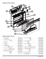
Page 6: ...LEDs Log Models 3001880100RP 11 Media LED Strip XHD23G 3001570100RP XHD26G 3001570700RP XHD28G 3001570300RP 12 Flame Screen XHD23 5902580400RP XHD26 5902580500RP XHD28 5902580600RP 13 Logset XHD23L 04...

Page 7: ...7 Wiring Diagram Logset or Media Bed LEDs On log models only...

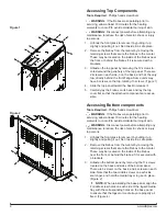
Page 8: ...the top cover flat so that the attached components are acces sible Accessing Bottom components Tools Required Phillips head screwdriver WARNING If the firebox was operating prior to servicing allow a...

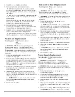
Page 9: ...ving parts by securing wires in cable ties or electrical tape 5 Reassemble the firebox Main Control Board Replacement Tools Required Phillips head screwdriver Pliers WARNING If the firebox was operati...

Page 10: ...ead screwdriver WARNING If the firebox was operating prior to servicing allow at least 10 minutes for the heating elements to cool off to avoid accidental burning of skin WARNING Disconnect power befo...

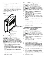
Page 11: ...ect power before attempting any maintenance to reduce the risk of electric shock or injury to persons 1 Follow the instructions for accessing the bottom components on pages 8 9 2 Locate the plastic LE...

Page 12: ...curing wires in cable ties or electrical tape 4 Drop the cable for the old thermistor as well as the wire of the new thermistor down at the same location as the old thermistor so that they will be acc...

Page 13: ...replaced Change batteries see Maintenance section Defective remote control Replace remote control Defective touchpad Replace touchpad Appearance Log set dim or not glowing Loose connection Check wiri...

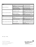
Page 14: ...cient space around the firebox Install feet if nec essary Buildup of dust debris Ensure that the exterior intake louvers and firebox cavity are free of dust debris Defective heater assembly Replace he...

Reviews: