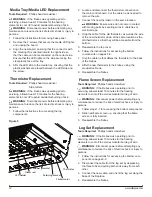
8
www.dimplex.com
Accessing Top Components
Tools Required:
Phillips head screwdriver
WARNING:
If the firebox was operating prior to
servicing, allow at least 10 minutes for the heating
elements to cool off to avoid accidental burning of skin.
WARNING:
Disconnect power before attempting any
maintenance to reduce the risk of electric shock or injury
to persons.
1. Unhook the front glass to remove it by pulling it up
slightly and pulling it out. Set it aside in a safe place.
2. Remove the firebox from the mantel by removing the
retaining screws that secure the firebox to the mantel.
These may be located on the inside of the firebox near
the front, or behind the firebox if it is secured with L-
brackets.
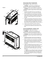
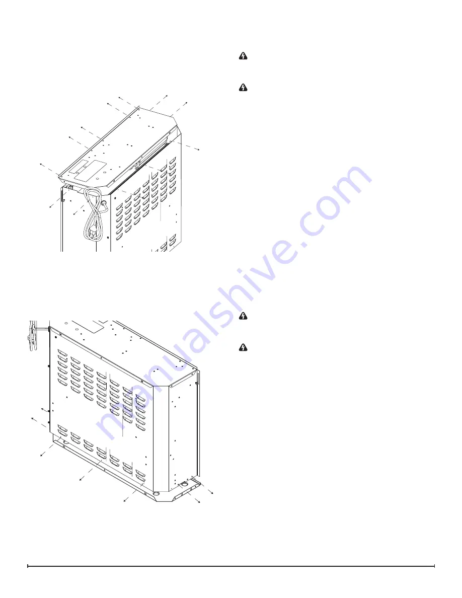
3. Unfasten the top panel by removing the 12 screws lo
-
cated around the periphery of the top panel. There are
2 screws on each side, 3 on the back, and 5 at the very
top, directly behind the front flange. Some units may
have 6 screws on the top, totaling 13 screws. (Figure 1)
4. Slide the top panel toward the back to release it.
5. Carefully lay the firebox on its back and lay the top
cover flat so that the attached components are acces
-
sible.
Accessing Bottom components
Tools Required:
Phillips head screwdriver
WARNING:
If the firebox was operating prior to
servicing, allow at least 10 minutes for the heating
elements to cool off to avoid accidental burning of skin.
WARNING:
Disconnect power before attempting any
maintenance to reduce the risk of electric shock or injury
to persons.
1. Unhook the front glass to remove it by pulling it up
slightly and pulling it out. Set it aside in a safe place.
2. Remove the firebox from the mantel by removing the
retaining screws that secure the firebox to the mantel.
These may be located on the inside of the firebox
near the front, or behind the firebox if it is secured with
L-brackets.
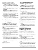
3. Unfasten the bottom panel by removing the 11 screws
located on the back and sides of the bottom panel.
There are 3 screws on the back, and 4 screws on each
side. Note that the two middle screws on each side
are longer, and hold the media tray or log set in place.
(Figure 2)
!
NOTE:
When reinstalling the base panel, align the
2 middle screw holes on each side of the logset/media
tray with the corresponding holes on the base panel
to ensure that the logset or media tray are properly af
-
fixed. (Figure 4)
Figure 1
Figure 2

