Instruction manual DNDS Kompakt
Products: safety
technique
DNDS KOMPAKT
Version 04 / 2011.03.16
page 7 from 20
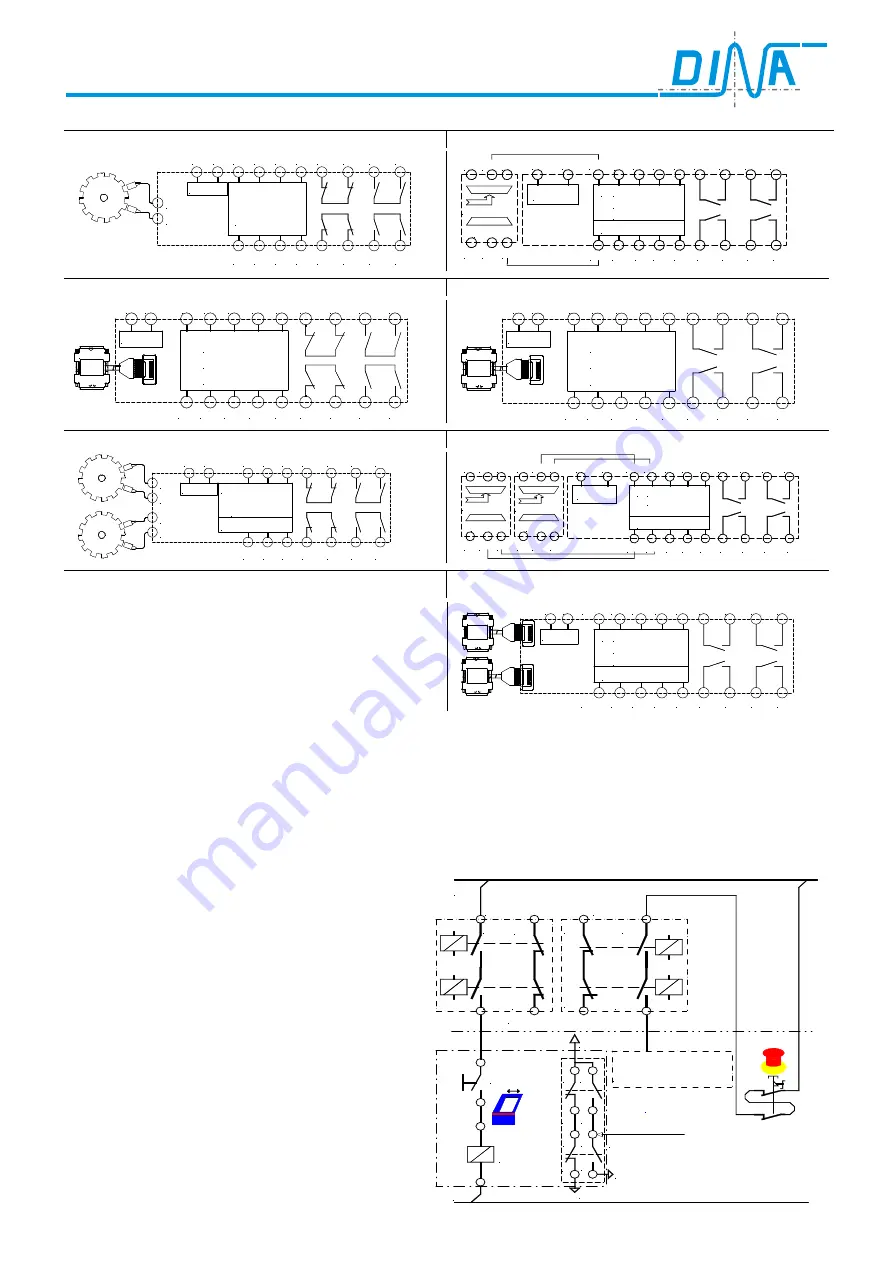
Circuit diagram
DNDS1C
Motion detection:
proximity sensors
DNDS 1D
Motion detection:
encoder
24VDC
Überwachung
Monitoring
Surveillance
A1 A2
F2 F3 F4 11 12 13 14
D2 D3 D4 21 22 23 24
IN1
IN2
F1
D1
24VDC
Surveillance
A1
A2
F1
13 14 23 24
33 34 43 44
IN1
Überwachung
Monitoring
1.
2.
F2 F3 F4
D1
IN2
D2 D3 D4
A1
A1 IA1
IA1
IA2
IA2
DNDA --/15
DNIA
DNDS 1FA
Motion detection:
encoder
DNDS 1GA
Motion detection:
encoder
24VDC
Surveillance
A1 A2
F1 F2 F3 F4 11
R
Überwachung
Monitoring
D1 D2 D3 D4
SH
12
13
14
21
22
23
24
Encoder
Meßsystem
24VDC
Surveillance
A1 A2
F1 F2 F3 F4 13
R
Überwachung
Monitoring
D1 D2 D3 D4
SH
14
23
24
33
34
43
44
Encoder
Meßsystem
DNDS 2C
Motion detection:
proximity sensors
DNDS 2D
Motion detection:
encoder
24VDC
Überwachung
Monitoring
Surveillance
A1 A2
IN1
D1 D2 D3 11 12 13 14
D4 D5 D6 21 22 23 24
IN2
IN3
IN4
1.
2.
DNIA
DNDA --/15
IA1
IA1
A1
A1
IA2
IA2
24VDC
Surveillance
A1
A2
IN2
13 14 23 24
33 34 43 44
IN1
Überwachung
Monitoring
1.
2.
D1 D2 D3
IN4
IN3
D4 D5 D6
A1
A1 IA1
IA1
IA2
IA2
DNDA --/15
DNIA
DNDS 2GA
Bewegungserfassung:
Encoder
Motion detection:
encoder
24VDC
Surveillance
A1 A2
D11 D12 D13 D14 13
SH11
Überwachung
Monitoring
1.
2.
D21 D22 D23 D24
SH21
14
23
24
33
34
43
44
Encoder
Meßsystem
Encoder
Meßsystem
DNDS 1C, 1FA, 2C, 2FA:
Applications of the outputs
STOP contacts: Standstill monitoring
If the protection cover is closed and one or more drives are in movement, the NO-contacts
13-14
open immediate-
ly. The NC-contacts
11-12
close. The LED STOP is not illuminated. The protection cover cannot be opened.
If all drives are stopped the contacts 13-14 close and 11-12 close. The protection cover can be opened. The LED
STOP is illuminated.
SPEED contacts: Motion monitoring
If the protection cover is closed, the F-inputs and
respectively the D-inputs of DNDS will be connected
to 24V DC via the switch of the protection cover. The
automatic mode will be monitored.
In case of the protection cover is open DNDS moni-
tors the standstill of all drives, if there is no function
mode selected.
If there is some function mode selected, as example
tool setting via SH-, R-input of DNDS, this function
mode will be monitored.
If one or more drives break the standstill as well as
the adjusted speed of the function mode, the NO
contacts
23-24
open and
21-22
close immediately.
The LED SPEED does not illuminated.
The drives will be stopped by emergency stop circuit
(STOP category 0). See principal schematic.
The contacts 23-24 close and 21-22 open again, if
the actual speed is 10% lower than the adjusted
speed. The LED SPEED illuminates.
Emergency stop
circuit
24
23
22
21
11
12
13
14
STOP
SPEED
L1
L2
to unlock
cover
Magnets
for bolt
DNDS
DNDS F- or D-inputs
Quit
Protection cover
switch
11 13
12 14
21 23
22 24
24V DC
CNC
Information contacts
Summary of Contents for DNDS 1C
Page 20: ......


