CLM–36
©
Dinel, s.r.o.
20
The level meter does not require any personnel for its operation. Follow-up displaying device is
used to inform the technological entity operating personnel on the measured substance level height
during the operation.
MAINTAINCE OF LEVEL METER
Maintenance of this equipment consists in verification of integrity of the level meter and of the sup-
ply cable. Depending on the character of the substance measured, we recommend to verify at least
once per year the clarity of the ultrasound transducer emitting field and to clean it, respectively. In
case any visible defects are discovered, the manufacturer or reseller of this equipment must be
contacted immediately.
15 . Use, manipulation and maintenance
It is forbidden to perform any modifications or interventions into the CLM–36 level meter
without manufacturer's approval. Potential repairs must be carried out by the manufacturer
or by a manufacturer authorized service organization only.
Installation, commissioning, operation and maintenance of the CLM–36 level meter has to
be carried out in accordance with this instruction manual; the provisions of regulations in
force regarding the installation of electrical equipment have to be adhered to.
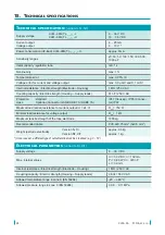
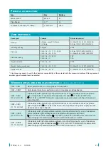
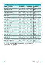
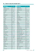
The level meter must be installed to prevent tensile overload of the rope electrode, see.
Specifications.
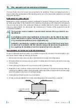
REPLACEMENT OF DEFECTIVE ELECTRONIC MODULE
In case of detected electronic failure it is possible to replace the electronic module directly in pro-
cess place of level meter by following procedure:
1. Disconnect connector and unscrew a nut (attention for inside connecting wires).
2. Defective electronic module pick up by pliers onto brass tie and remove by tensile from housing
of level meter.
3. Check placing of white seal O-ring in housing and on pressure ring.
4. Repaired or new electronic module return back into housing of level meter and press down by
clamping ring (attention that contact pin will be a little open before insertion and contact springs
were not pressed under level of electronic casing).
5. Check placing of black seal O-ring on connector.
6. Screw a nut back (attention for inside connecting wires) and connect the connector.
contact pin
contact springs
brass tie
electronic module
cover
trimmers
Fig. 12: Side view of the electronic module


