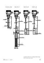
CLM–70
©
Dinel, s.r.o.
4
Capacitive level meters
CLM-70
are compact measuring devices consisting of the level meter
body and a measuring electrode. The level meter body contains measurement electronics
and a display module. The electronics measure the electrical capacity of the electrode system,
which is dependent on the level height. The level meter’s electrical output corresponds to the
capacity (level height) and the measured data are shown on the meter’s display.
The level meter can be adjusted by the display module positioned under the transparent lid.
The level meter has 4–20 mA current output with HART
®
communication. The level meter is
power supplied using a cable connected to the terminal block located under the display and
adjustment module.
Level meters are available in several measuring electrode modifications (rod and rope-type
electrodes). Electrodes may be coated with insulation, which is important for their functioning
in the case of adherent, electrically conductive and aggressive media. Rod electrodes are
also available in a version provided with a reference tube or a pair of parallel electrodes for
measuring liquids in non-conductive tanks.
All operations described in this instruction manual have to be carried out by trained
personnel or by an accredited person only. Warranty and post warranty service must
be exclusively carried out by the manufacturer.
Improper use, installation or set-up of the sensor can lead to crashes in the ap-
plication.
The manufacturer is not responsible for improper use, loss of work caused by either
direct or indirect damage, and for expenses incurred at the time of installation or
during the period of use of the level sensors.
To ensure maximum safety of control processes, we have defined the following safety instruc-
tions and information. Each instruction is labelled with the appropriate pictogram.
Alert, warning, danger
This symbol informs you about particularly important instructions for installation and
operation of equipment or dangerous situations that may occur during the installation
and operation. Not observing these instructions may cause disturbance, damage or de
-
struction of equipment or may cause injury.
Information
This symbol indicates particularly important characteristics of the device.
Note
This symbol indicates helpful additional information.
U
sed
symbols
1 .
s
afety
2 .
b
asiC
desCription
Summary of Contents for CLM-70
Page 2: ......


