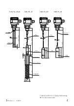
CLM–70
©
Dinel, s.r.o.
8
BASIC INFO
• The level meters with an insulated electrode are equipped with a protective cap at the
electrode end, which must be removed before installation.
•
The level meters are mounted vertically into the upper lid of the tank or hopper or on fixing
brackets using a welding flange for a fixing nut or a Clamp-type flange.
• When installing the level meter in a metal tank or hopper, the housing is not necessary to
be grounded separately.
• In the case of installation in concrete sumps or silos, the level meter is advisable to
be installed on an auxiliary metal structure (bracket, lid, etc.) and then connected to
a permanently submerged metal object or steel reinforcements in concrete (armouring).
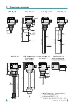
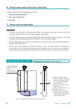
E - electrode length [mm] –
select so that the electrode
end is submerged at least
20 mm below the lowest
measured level
h - distance from the bottom
– at least 50 mm
a - distance from the wall – at
least approx. E/20
d - diameter of the auxiliary
tubular vessel – at least 40
+ E/20 (smaller dimensions
must be discussed)
Auxiliary electrode
width = minimum
30 mm
(required for non-
metal vessels only)
Fig. 1: Installation of level meters with rod electrodes
6 .
i
nstallation
and
pUtting
into
operation
This procedure has the following three steps:
• i
nstallation
instrUCtions
• e
leCtriCal
ConneCtion
• s
ettings
7 .
i
nstallation
instrUCtions
METAL AND NON-METAL VESSELS
APPLIES TO: CLM-70_-10, 11, 12, 13
Summary of Contents for CLM-70
Page 2: ......


