DLM–35
©
Dinel, s.r.o.
9
6 . Electrical connection
The positive pole of the supply voltage (+U) is connected to the brown wire BN or pin connector
no.1, the negative pole (0 V) is connected to the blue wire BU or pin connector no. 3 and output
voltage (Uout) to the black wire BK or pin connector no. 4.
Wiring diagrams are provided in the figures below 4 and 5.
Note: In case of strong ambient electromagnetic interference, paralleling of conductors with power
distribution, or for the distribution to distance over 30 m, we recommend using shielded cable.
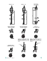
Level meters DLM-35 with type of cable outlet A, B, V or H are connected to assessing units
permanently connected by PVC cable. Variant diagrams are provided on page 7.
Level meters DLM-35 with connection method type C (see page 7) are connected to assessing
units by means of a connector socket with compression cable (length 2 or 5 m), or by means of
a connector socket without cable (see accessories), the connector is not part of the sensor. In this
case the cable is connected to the inside pins of the socket according to figure 6. The recommended
diameter of this cable is 4 to 6 mm (the recommended cross-sectional area is 0.25 to 0.5 mm²).
The length of the cable for the Xi, XiT, XiM, XiMT variations must be selected with respect to the
maximum permitted parameters (usually inductance and capacity) of the outside intrinsically safe
circuit of supply units IRU-420.
Electrical connection can only be made when de-energized!
The source of the power voltage must comprise of a stabilised safe low power source with
galvanic separation. In the event that a switch-mode power supply is used, it is essential
that its construction effectively suppresses common mode interference on the secondary
side. In the event that the switch-mode power supply is equipped with a PE safety terminal, it
must be unconditionally grounded! Spark-safe devices type DLM–35Xi (XiT, XiM, XiMT) must
be powered from a spark-safe power source meeting the above-mentioned requirements.
+
-
+
-
0 V (3)
+U (1)
BN ( )
1
BU ( )
2
mA
+U
0V
V
+U
0V
U
Uout
V
+U
0V
U
Uout
mA
+U
0V
+U
0V
BN (1)
BU (2)
BK (3)
+U
0V
BN (1)
BU (3)
BK (4)
BN ( )
1
BU (3)
BN ( )
1
BU ( )
2
BK (3)
BN ( )
1
BU (3)
BK (4)
BN ( )
1
BU ( )
2
mA
+U
0V
mA
+U
0V
BN ( )
1
BU (3)
BN ( )
1
BU ( )
2
mA
+U
0V
V
+U
0V
U
Uout
V
+U
0V
U
Uout
mA
+U
0V
+U
0V
BN (1)
BU (2)
BK (3)
+U
0V
BN (1)
BU (3)
BK (4)
BN ( )
1
BU (3)
BN ( )
1
BU ( )
2
BK (3)
BN ( )
1
BU (3)
BK (4)
BN ( )
1
BU ( )
2
mA
+U
0V
mA
+U
0V
BN ( )
1
BU (3)
Fig. 4: Connection diagrams and interior view
of connector of level meter DLM (variant - I)
Fig. 5: Connection diagrams and interior view
of connector of level meter DLM (variant - U)
0 V (3)
+U (1)
Fig. 6: Inside of the
connector socket
(variant “C”)
Uout (BK)
0V (BU)
+U (BN)
Legend:
(1...) – terminal numbers
connector sockets
BN – brown
BU – blue
BK – black
Uout (4)


