HLM–35
©
Dinel, s.r.o.
8
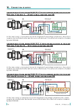
In case of use cable with capillary
connect the positive pole (+U) of the power supply
to the red wire RD, or connector pin no. 1, the negative pole (0 V) to the blue wire BU, or
connector pin no. 3, and the output voltage (U
out
) to the black wire BK, or connector pin no.
4. Connection diagrams are provided in the figures below.
In case of use cable without capillary
connect the positive pole (+U) of the power supply
to the brown wire BR, or connector pin no. 1, the negative pole (0 V) to the blue wire BU, or
connector pin no. 3, and the output voltage (U
out
) to the black wire BK, or connector pin no.
4. Connection diagrams are provided in the figures below.
(X) – Connector terminal numbers
Cable wire colours with
a pressed connector:
BR – brown
BU – blue
Cable wire colours
with capillary:
RD – red
BU – blue
---- – shielding
0 V (3)
+U (1)
Level meter connection with current output
BR (1)
RD
BU (3)
U
out
(4)
0 V (3)
+U (1)
Level meter connection with current output
(X) – Connector terminal numbers
Cable wire colours with
a pressed connector:
BR – brown
BK – black
BU – blue
Cable wire colours
with capillary:
RD – red
BU – blue
BK – black
---- – shielding
BR (1)
RD
BK (4)
BU (3)


