培训手册
Training Manual
电气原理图
Electrical Schematic
JCPT- DCS
www.cndingli.com
6-4
A
H
J
S
A
J
H
S
A
J
H
S
A
H
J
S
1
2
3
5
4
1
2
3
4
5
CP5
CP4
1
2
3
5
4
003 RD
GND BK
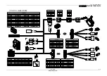
Main Circuit
CP3
RD
BU
BK
Potentiometer
RD
WH+GN
BK
Pressure Sensor
YE
GN
Lift Down Valve
003
R
D
WH
Charging Protection
Charger
A
B
C
C
A
B
Drive Controller
Platform Ccntrol Module
Valves
Lift Up Valve
Steer Left Valve
Steer Right Valve
DC Contactor
-BATT
1
2
Beacon
RD
BU
WH
WH
Pothole Switch
11
12
NC.
Pothole Switch
11
12
NO.
BK
BK
A22 WH
GND BK
DC Contactor
Drive Motor
BK
BK
RD
RD
Brake(Left) +
Brake(Left) -
Brake(Right) +
Brake(Right) -
DC Contactor
A2 WH
A5 WH
A4 WH
GND BK
GND BK
GND BK
PW
OU
T
RD
002
R
D
00
3A
R
D
GN
D
BK
85
86
87
30
Relay
CP1
CP2
1
14
15
28
29
42
43
56
1
7
13
8
19
26
14
20
2A
2
1
00
3A
R
D
10A
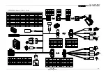
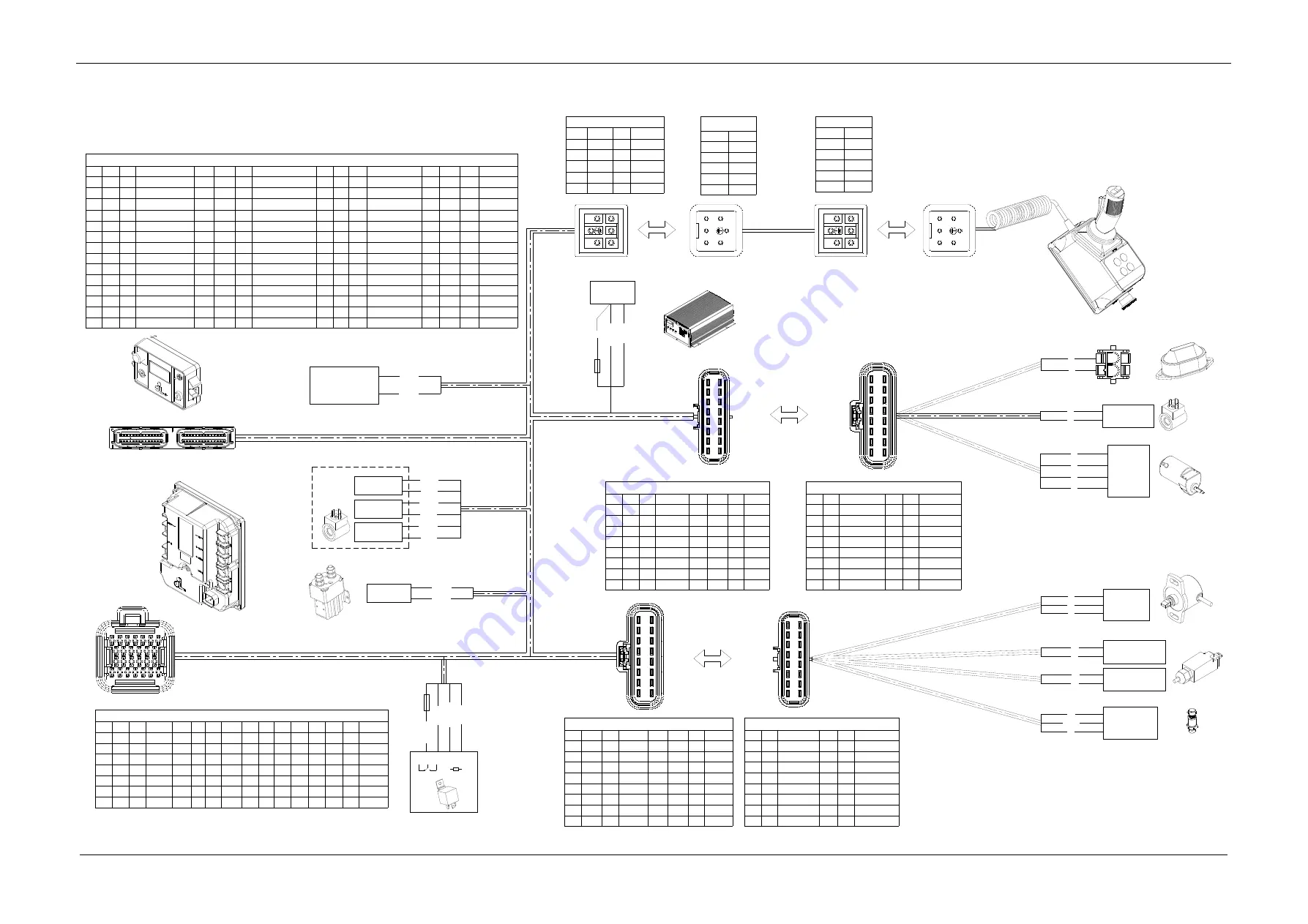
Delphi Pin
NO. Colour
Place
NO. Colour
Place
A
/
/
J
/
/
B
/
/
K
/
/
C
RD
Pressure Sensor
L
WH
Pressure Sensor
D
RD
Potentiometer
M
GN
Pressure Sensor
E
WH
Pothole Switch
N
YE
Potentiometer
F
WH
Pothole Switch
P
BK
Potentiometer
G
/
/
R
/
/
H
/
/
S
BK
Pressure Sensor
Delphi Pin
NO.
ID.
Colour
Place
NO.
ID.
Colour
Place
A
002
RD
Power
J
A32
WH
ECU
B
002
RD
Power
K
A33
WH
ECU
C
002
RD
Power
L
A45
WH
ECU
D
002
RD
Power
M
A46
WH
ECU
E
002
RD
Power
N
A48
WH
ECU
F
A29
WH
ECU
P
GND
BK
Ground
G
A7
WH
ECU
R
GND
BK
Ground
H
A34
WH
ECU
S
GND
BK
Ground
Drive Controller Pin
NO.
ID. Colour
Place
NO.
ID. Colour Place
NO.
ID. Colour Place
NO.
ID. Colour
Place
1
A23
WH
ECU
8
002
RD
Power
14
GND
BK
Ground
20
/
/
/
2
A24
WH
ECU
9
002
RD
Power
15
GND
BK
Ground
21
/
/
/
3
/
/
/
10
002
RD
Power
16
GND
BK
Ground
22
/
/
/
4
/
/
/
11
/
/
/
17
/
/
/
23
A20
WH
ECU
5
CANL
GN
ECU
12
/
/
/
18
/
/
/
24
A20
WH
ECU
6
CANL
GN
ECU
13
/
/
/
19
/
/
/
25
A19
WH
ECU
7
CANH
YE
ECU
26
/
/
/
Delphi Pin
NO. Colour
Place
NO. Colour
Place
A
/
/
J
BK
Brake(Left) -
B
/
/
K
BK
Brake(Right) -
C
YE
Lift Down Valve
L
GN
Lift Down Valve
D
RD
Brake(Left) +
M
/
/
E
RD
Brake(Right) +
N
/
/
F
/
/
P
/
/
G
RD
Beacon
R
/
/
H
BU
Beacon
S
/
/
Delphi Pin
NO.
ID. Colour
Place
NO.
ID.
Colour
Place
A
002
RD
Power
J
GND
BK
Ground
B
002
RD
Power
K
GND
BK
Ground
C
A1
WH
ECU
L
GND
BK
Ground
D
A25
WH
ECU
M
GND
BK
Ground
E
A26
WH
ECU
N
/
/
/
F
A17
WH
ECU
P
/
/
/
G
A18
WH
ECU
R
/
/
/
H
GND
BK
Ground
S
/
/
/
ECU Pin
NO.
ID. Colour
Place
NO.
ID.
Colour
Place
NO.
ID. Colour
Place
NO.
ID.
Colour
Place
1
A1
WH
Lift Down Valve
15
A15
RD
Power
29
A29
WH
Pothole Switch
43
A43
RD
Power
2
A2
WH
Lift Up Valve
16
/
/
/
30
/
/
/
44
A44
RD
Power
3
A3
WH
Power_key
17
A17
WH
Horn
31
A31
WH
Power_key
45
A45
WH
Pressure Sensor
4
A4
WH
Steer Right Valve
18
A18
WH
Beacon
32
A32
WH
Anti-collision Switch
46
A46
WH
Pressure Sensor
5
A5
WH
Steer Left Valve
19
A19
WH
TM-Main Contactor
33
A33
WH
TILT sensor
47
/
/
/
6
/
/
/
20
A20
WH
TM-Brake
34
A34
WH
Pedal Deadman Switch
48
A48
WH
Potentiometer
7
A7
WH
Indoor/Outdoor Switch
21
/
/
/
35
/
/
/
49
/
/
/
8
/
/
/
22
A22
WH
Main Contactor coil
36
/
/
/
50
/
/
/
9
/
/
/
23
A23
WH
TM-Motor(Right) Feedback
37
/
/
/
51
/
/
/
10
A10
BK
Ground
24
A24
WH
TM-Motor(Left) Feedback
38
/
/
/
52
A52
GY
PCU Power
11
/
/
/
25
A25
WH
Left Motor Brake Coil
39
/
/
/
53
A53
GY
PCU Power
12
A12
GN
CAN_L
26
A26
WH
Right Motor Brake Coil
40
A40
YE
CAN_H
54
A54
BK
Ground
13
/
/
/
27
A27
RD
Power
41
A41
RD
Power
55
A55
BK
Ground
14
A14
RD
Power
28
A28
BK
Ground
42
A42
RD
Power
56
A56
BK
Ground
SIBAS Pin
NO.
ID.
Colour
Place
1
A52
GY
ECU
2
PWOUT
RD
Relay
3
GND
BK
Ground
4
CANH
YE
ECU
5
CANL
GN
ECU
SIBAS Pin
NO.
Colour
1
RD
2
GN
3
WH
4
YE
5
BU
SIBAS Pin
NO.
Colour
1
RD
2
GN
3
WH
4
YE
5
BU
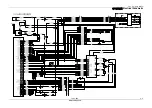
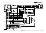
JCPT0607DCS Harness-Control Circuit
ECU
1
2
3
4
5
Summary of Contents for JCPT DCS Series
Page 2: ......
Page 16: ......
Page 17: ...培训手册 Training Manual 操作 Operation JCPT DCS www cndingli com 2 1 操作 Operation ...
Page 26: ......
Page 36: ......
Page 68: ......
Page 85: ...培训手册 Training Manual 常规保养 Daily Maintenance JCPT DCS www cndingli com 9 5 ...
Page 86: ......

