ENGINE
【
6-23
】
INSPECTION
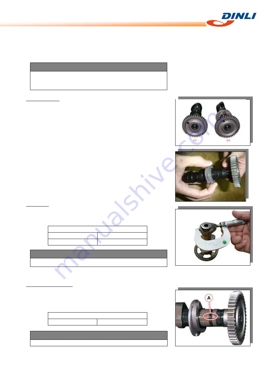
Camshaft
and
Cylinder
Head
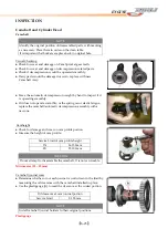
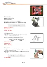
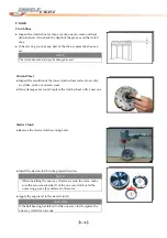
Camshaft
NOTE
Identify
the
original
position
of
disassembled
parts,
with
marking
as
necessary.
Place
them
in
order
on
the
clean
table.
It
is
important
that
buckets
are
place
back
in
original
hole.
Visual
Checking
●
Check
for
wear
and
damage
on
Cam
Sprocket
gear
teeth.
●
Check
for
wear
and
damage
on
decompression
related
parts.
●
Check
if
decompression
would
be
operated
smoothly.
●
If
any
parts
would
be
damaged
or
worn,
replace
with
new
Camshaft
Assy.
●
Move
the
automatic
decompression
weight
by
hand
to
inspect
if
it
is
operating
smoothly.
●
If
it
does
not
operate
smoothly,
or
the
spring
occur
elastic
fatigue,
replace
the
camshaft/automatic
decompression
assembly
with
a
new
one.
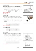
Camheight
●
Check
for
damage
and
wear
on
cam
profile
portion.
●
Measure
the
height
of
cam
profile.
Service
Limit
of
cam
profile
height
IN
36.150
mm
EX
35.100
mm
Micrometer
(25
–
50
mm)
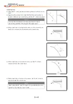
Camshaft
journal
wear
●
Determine
whether
or
not
each
journal
is
worn
down
to
the
limit
by
measuring
the
oil
clearance
with
the
camshaft
installed
in
place.
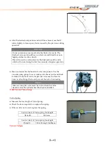
●
Use
the
plastigauge
[A]
to
read
the
clearance
at
the
widest
portion.
Oil
clearance
at
cam
journal
portion
Service
Limit
0.150
mm
Plastigauge
CAUTION
Do
not
attempt
to
disassemble
the
camshaft.
It
is
not
serviceable.
NOTE
Install
camshaft
journal
holders
to
their
original
positions.
Summary of Contents for DL-702 2008
Page 1: ...FOREWORD INDEX 0 0...
Page 41: ...3 11 BRAKE...
Page 180: ...6 70 ENGINE Install the starter motor...
Page 201: ...7 21 COOLING AND LUBRICATION SYSTEM Engine Lubrication System Chart...
Page 202: ...7 22 COOLING AND LUBRICATION SYSTEM Engine Lubrication System 1 2 3 1 2 3 1 2 3...
Page 203: ...7 23 COOLING AND LUBRICATION SYSTEM 1 2 3...
Page 235: ...7 32 ELECTRICAL SYSTEM Wiring Diagram...
Page 236: ...7 33 ELECTRICAL SYSTEM Wiring Diagram...
Page 237: ...7 34 7 34 ELECTRICAL SYSTEM ELECTRICAL SYSTEM...
Page 238: ...7 35 ELECTRICAL SYSTEM NOTE...
Page 240: ...9 2 PERIODIC MAINTENANCE...
Page 246: ...9 8 PERIODIC MAINTENANCE Intake Side...
Page 247: ...9 9 PERIODIC MAINTENANCE Exhaust Side Side...
Page 270: ...9 32 PERIODIC MAINTENANCE 1 2 3 4 18 19 12 16 17 21 13 14 15 22 23 5 6 7 8 9 12 10 11 20...

