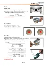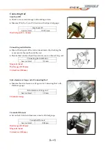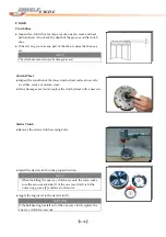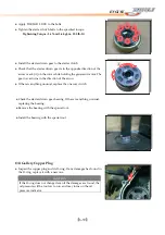
【
6-24
】
ENGINE
●
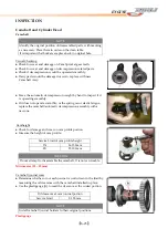
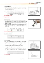
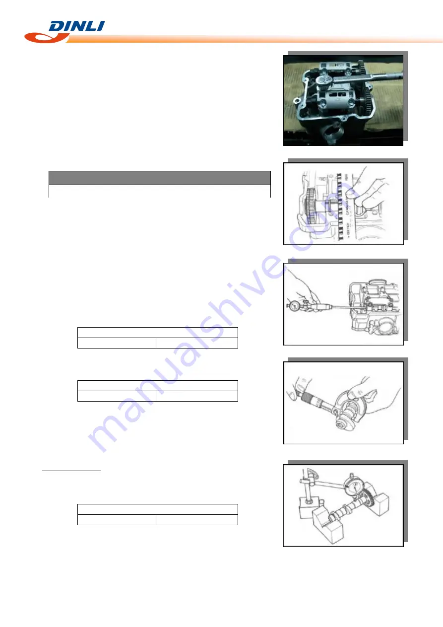
Tighten
the
camshaft
journal
holder
bolts
evenly
and
diagonally
to
the
specified
torque.
Tightening
Torque:
10N
‐
m
(1.0
kgf
‐
m,
7.0
lb
‐
ft)
NOTE
Do
not
rotate
the
camshaft
with
the
plastigauge
in
place.
●
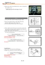
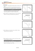
Remove
the
camshaft
holders,
and
read
the
width
of
the
compressed
plastigauge
with
envelope
scale.
●
This
measurement
should
be
taken
at
the
widest
part.
●
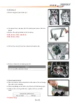
If
the
camshaft
journal
oil
clearance
measured
exceeds
the
limit,
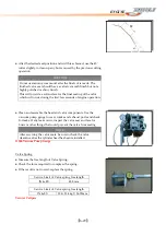
measure
the
inside
diameter
of
the
camshaft
journal
holder
and
outside
diameter
of
the
camshaft
journal.
●
Replace
the
camshaft
or
the
cylinder
head
depending
upon
which
one
exceeds
the
specification.
ID
of
cam
journal
portion
Standard
(IN
&
EX)
23.000
‐
23.021
mm
Small
Bore
Gauge
(18
–
35
mm)
Dial
Gauge
(1/1000
mm,
1
mm)
OD
of
Camshaft
journal
portion
Standard
(IN
&
EX)
22.959
‐
22.980
mm
Micrometer
Camshaft
Runout
●
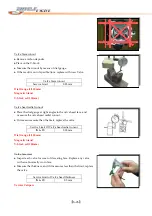
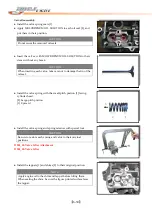
Measure
the
runout
from
using
the
dial
gauge.
●
Replace
the
camshaft
if
the
runout
exceeds
the
limit.
Service
Limit
Of
Camshaft
Runout
IN
&
EX
0.10
mm
Dial
Gauge
(1/1000
mm,
10
mm)
Magnetic
Stand
V
‐
block
Set
(100
mm)
Summary of Contents for DL-702 2008
Page 1: ...FOREWORD INDEX 0 0...
Page 41: ...3 11 BRAKE...
Page 180: ...6 70 ENGINE Install the starter motor...
Page 201: ...7 21 COOLING AND LUBRICATION SYSTEM Engine Lubrication System Chart...
Page 202: ...7 22 COOLING AND LUBRICATION SYSTEM Engine Lubrication System 1 2 3 1 2 3 1 2 3...
Page 203: ...7 23 COOLING AND LUBRICATION SYSTEM 1 2 3...
Page 235: ...7 32 ELECTRICAL SYSTEM Wiring Diagram...
Page 236: ...7 33 ELECTRICAL SYSTEM Wiring Diagram...
Page 237: ...7 34 7 34 ELECTRICAL SYSTEM ELECTRICAL SYSTEM...
Page 238: ...7 35 ELECTRICAL SYSTEM NOTE...
Page 240: ...9 2 PERIODIC MAINTENANCE...
Page 246: ...9 8 PERIODIC MAINTENANCE Intake Side...
Page 247: ...9 9 PERIODIC MAINTENANCE Exhaust Side Side...
Page 270: ...9 32 PERIODIC MAINTENANCE 1 2 3 4 18 19 12 16 17 21 13 14 15 22 23 5 6 7 8 9 12 10 11 20...

