ENGINE
【
6-25
】
Cylinder
head
●
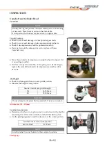
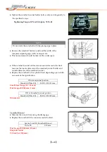
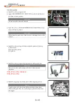
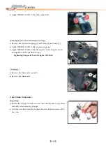
Remove
tappets
[1]
and
shims
[2].
●
Use
special
tools,
compress
the
Valve
Spring
and
remove
the
valve
keeper.
●
Remove
the
spring
retainer
and
valve
spring.
D005_01
‐
Valve
Lifter
Attachment
D005_02
‐
Valve
Lifter
●
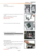
Pull
out
the
valve
[3]
from
the
combustion
chamber
side.
●
Remove
oil
seals
[1]
and
spring
seats
[2].
NOTE
Do
not
reuse
the
removed
oil
seals.
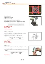
Cylinder
head
distortion
●
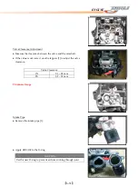
Clean
and
remove
carbon
deposits
from
the
surface.
Never
damage
the
surface
when
cleaning.
●
Place
straightedge
on
the
surface,
and
check
with
thickness
gauge.
●
If
the
result
is
out
of
specifications,
replace
with
new
Cylinder
Head.
Cylinder
Head
Distortion
Service
Limit
0.05
mm
Thickness
Gauge
Summary of Contents for DL-702 2008
Page 1: ...FOREWORD INDEX 0 0...
Page 41: ...3 11 BRAKE...
Page 180: ...6 70 ENGINE Install the starter motor...
Page 201: ...7 21 COOLING AND LUBRICATION SYSTEM Engine Lubrication System Chart...
Page 202: ...7 22 COOLING AND LUBRICATION SYSTEM Engine Lubrication System 1 2 3 1 2 3 1 2 3...
Page 203: ...7 23 COOLING AND LUBRICATION SYSTEM 1 2 3...
Page 235: ...7 32 ELECTRICAL SYSTEM Wiring Diagram...
Page 236: ...7 33 ELECTRICAL SYSTEM Wiring Diagram...
Page 237: ...7 34 7 34 ELECTRICAL SYSTEM ELECTRICAL SYSTEM...
Page 238: ...7 35 ELECTRICAL SYSTEM NOTE...
Page 240: ...9 2 PERIODIC MAINTENANCE...
Page 246: ...9 8 PERIODIC MAINTENANCE Intake Side...
Page 247: ...9 9 PERIODIC MAINTENANCE Exhaust Side Side...
Page 270: ...9 32 PERIODIC MAINTENANCE 1 2 3 4 18 19 12 16 17 21 13 14 15 22 23 5 6 7 8 9 12 10 11 20...

