ENGINE
【
6-27
】
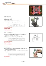
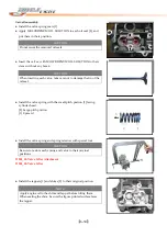
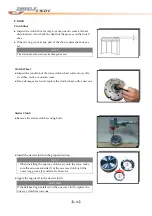
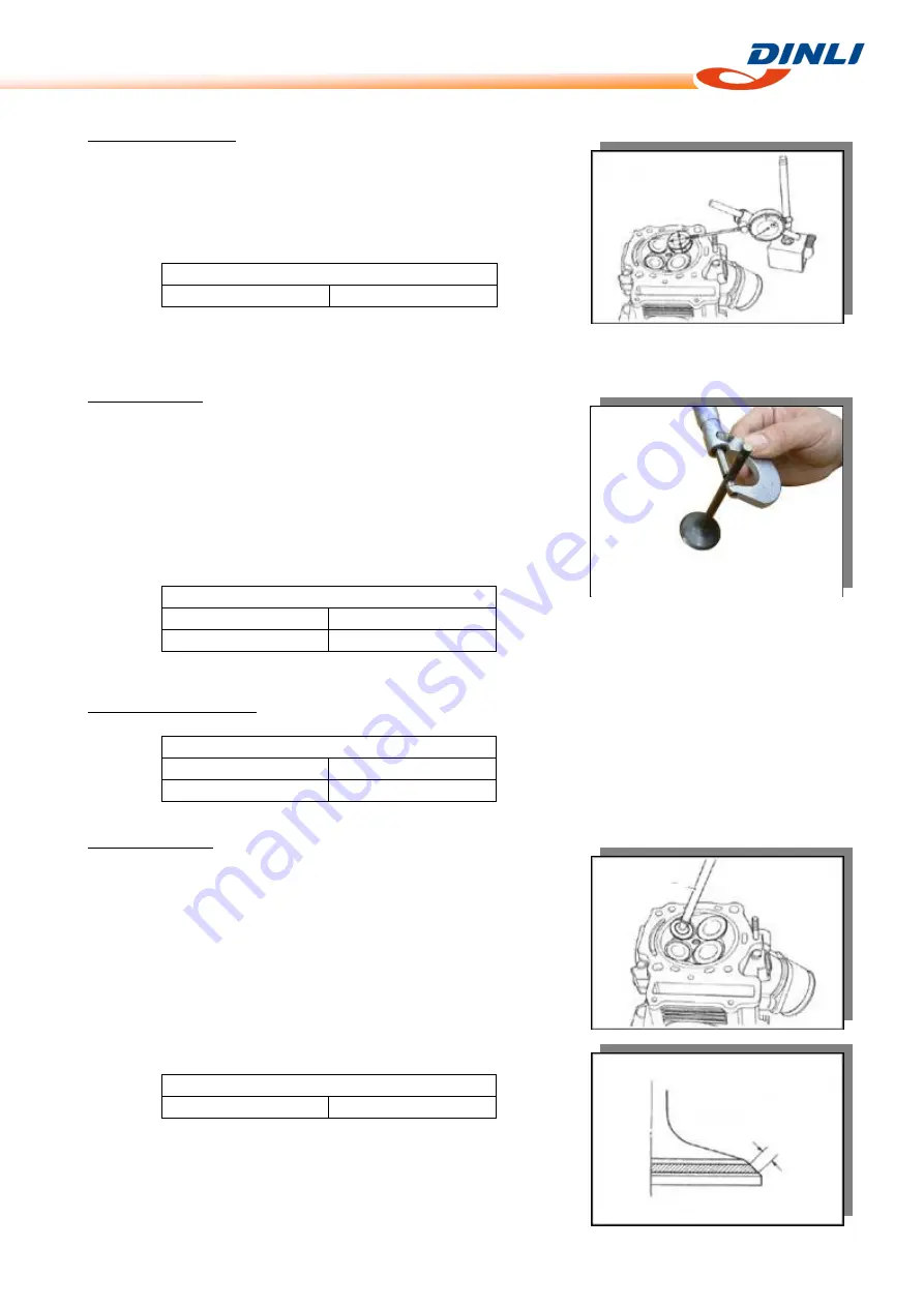
Valve
stem
deflection
●
Lift
the
valve
about
8
mm
from
the
valve
seat.
Measure
the
valve
stem
deflection
in
two
directions,
perpendicular
to
each
other,
by
positioning
the
dial
gauge.
●
If
the
deflection
measured
exceeds
the
limit,
then
determine
whether
the
valve
or
the
guide
should
be
replaces
with
a
new
one.
Service
Limit
of
Valve
stem
deflection
IN
&
EX
0.35
mm
Dial
Gauge
(1/100
mm)
Magnetic
Stand
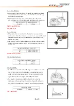
Valve
stem
wear
●
If
the
valve
stem
is
worn
down
to
the
limit,
as
measured
with
a
micrometer,
where
the
clearance
is
found
to
be
in
excess
of
the
limit
indicated,
replace
the
valve;
if
the
stem
is
within
the
limit,
then
replace
the
guide.
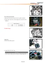
●
Measure
OD
of
Valve
Stem
sliding
portion
at
total
6
points;
upper,
middle
and
lower
positions
and
X
‐
and
Y
‐
directions,
by
means
of
micrometer.
Service
Limit
of
Valve
Guide
OD
IN
5.450
‐
5.465
mm
EX
5.430
‐
5.445
mm
Micrometer
(0
–
25
mm)
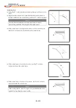
Valve
Guide
Attachment
Valve
Guide
Attachment
Height
IN
12.7
mm
EX
12.5
mm
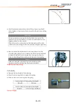
Valve
Seat
Width
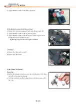
●
Coat
the
valve
seat
uniformly
with
bright
color.
Fit
the
valve
and
tap
the
coated
seat
with
the
valve
face
in
a
rotating
manner,
in
order
to
obtain
a
clear
impression
of
the
seating
contact.
In
this
operation,
use
the
valve
lapper
to
hold
the
valve
head.
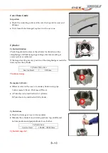
●
The
ring
like
dye
impression
left
on
the
valve
face
must
be
continuous
without
any
break.
In
addition,
the
width
of
the
dye
ring,
which
is
visualized
seat
“width”,
must
fit
the
specification.
Valve
Seat
Width
Standard
0.9
mm
–
1.1
mm
Valve
Lapper
Set
W
Summary of Contents for DL-702 2008
Page 1: ...FOREWORD INDEX 0 0...
Page 41: ...3 11 BRAKE...
Page 180: ...6 70 ENGINE Install the starter motor...
Page 201: ...7 21 COOLING AND LUBRICATION SYSTEM Engine Lubrication System Chart...
Page 202: ...7 22 COOLING AND LUBRICATION SYSTEM Engine Lubrication System 1 2 3 1 2 3 1 2 3...
Page 203: ...7 23 COOLING AND LUBRICATION SYSTEM 1 2 3...
Page 235: ...7 32 ELECTRICAL SYSTEM Wiring Diagram...
Page 236: ...7 33 ELECTRICAL SYSTEM Wiring Diagram...
Page 237: ...7 34 7 34 ELECTRICAL SYSTEM ELECTRICAL SYSTEM...
Page 238: ...7 35 ELECTRICAL SYSTEM NOTE...
Page 240: ...9 2 PERIODIC MAINTENANCE...
Page 246: ...9 8 PERIODIC MAINTENANCE Intake Side...
Page 247: ...9 9 PERIODIC MAINTENANCE Exhaust Side Side...
Page 270: ...9 32 PERIODIC MAINTENANCE 1 2 3 4 18 19 12 16 17 21 13 14 15 22 23 5 6 7 8 9 12 10 11 20...

