ENGINE
【
6-31
】
2
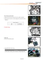
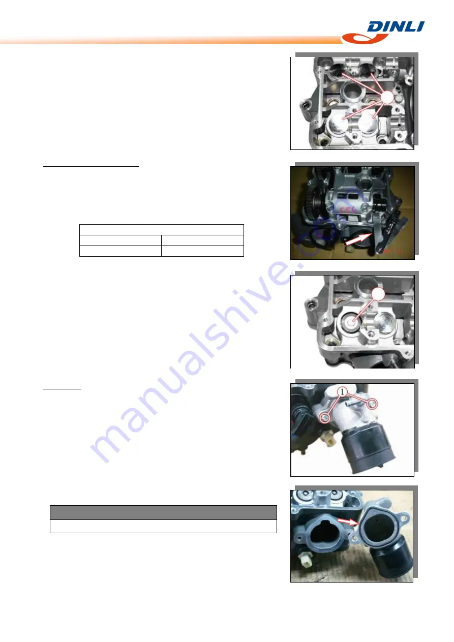
Valve
Clearance
Adjustment
●
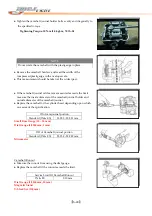
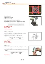
Measure
the
clearance
between
the
valve
and
the
camshaft.
●
If
the
value
is
not
correct,
use
the
tappets
[1]
to
adjust
the
valve
clearance.
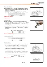
Valve
Clearance
IN
0.1
–
0.2
mm
EX
0.2
–
0.3
mm
Thickness
Gauge
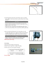
1
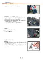
Intake
Pipe
●
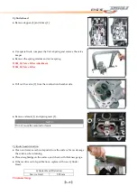
Remove
the
intake
pipe
[1].
●
Apply
GREASE
to
the
O
‐
ring.
CAUTION
Use
the
new
O
‐
ring
to
prevent
air
from
sucking
through
joint.
Summary of Contents for DL-702 2008
Page 1: ...FOREWORD INDEX 0 0...
Page 41: ...3 11 BRAKE...
Page 180: ...6 70 ENGINE Install the starter motor...
Page 201: ...7 21 COOLING AND LUBRICATION SYSTEM Engine Lubrication System Chart...
Page 202: ...7 22 COOLING AND LUBRICATION SYSTEM Engine Lubrication System 1 2 3 1 2 3 1 2 3...
Page 203: ...7 23 COOLING AND LUBRICATION SYSTEM 1 2 3...
Page 235: ...7 32 ELECTRICAL SYSTEM Wiring Diagram...
Page 236: ...7 33 ELECTRICAL SYSTEM Wiring Diagram...
Page 237: ...7 34 7 34 ELECTRICAL SYSTEM ELECTRICAL SYSTEM...
Page 238: ...7 35 ELECTRICAL SYSTEM NOTE...
Page 240: ...9 2 PERIODIC MAINTENANCE...
Page 246: ...9 8 PERIODIC MAINTENANCE Intake Side...
Page 247: ...9 9 PERIODIC MAINTENANCE Exhaust Side Side...
Page 270: ...9 32 PERIODIC MAINTENANCE 1 2 3 4 18 19 12 16 17 21 13 14 15 22 23 5 6 7 8 9 12 10 11 20...

