ENGINE
【
6-59
】
●
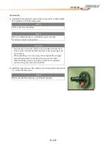
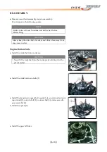
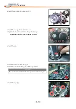
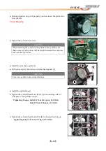
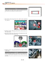
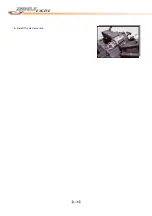
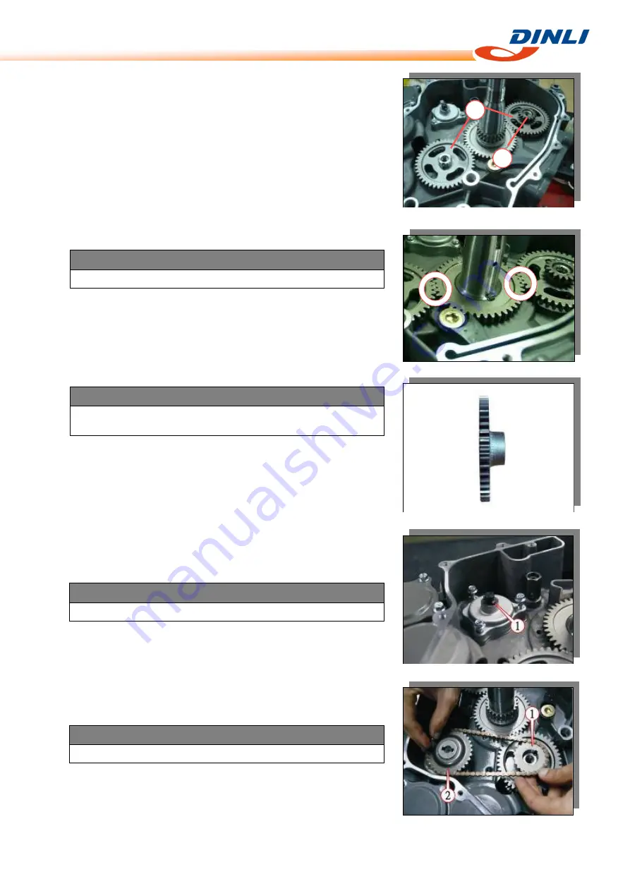
Install
the
crank
balancer
driven
gears
[1]
and
water
pump
drive
gear
[2].
1
2
NOTE
Align
the
punched
marks
as
shown.
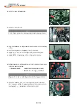
NOTE
Pay
attention
to
the
direction
of
the
water
pump
drive
gear
and
oil
pump
drive
gear.
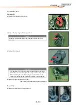
●
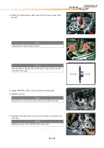
Apply
THREAD
LOCK
to
the
oil
pump
mounting
bolts.
●
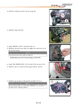
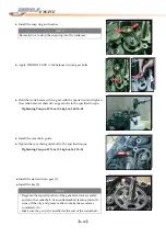
Install
the
pin
[1].
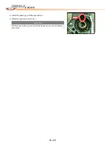
●
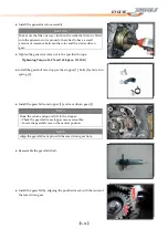
Install
the
oil
pump
drive
gear
[1]
and
oil
pump
driven
gear
with
chain
[2].
Inside
Outside
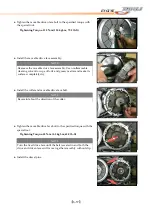
NOTE
Be
careful
not
to
drop
the
washer
and
pin
into
the
crankcase.
NOTE
Both
gears
have
to
be
installed
at
the
same
time.
Summary of Contents for DL-702 2008
Page 1: ...FOREWORD INDEX 0 0...
Page 41: ...3 11 BRAKE...
Page 180: ...6 70 ENGINE Install the starter motor...
Page 201: ...7 21 COOLING AND LUBRICATION SYSTEM Engine Lubrication System Chart...
Page 202: ...7 22 COOLING AND LUBRICATION SYSTEM Engine Lubrication System 1 2 3 1 2 3 1 2 3...
Page 203: ...7 23 COOLING AND LUBRICATION SYSTEM 1 2 3...
Page 235: ...7 32 ELECTRICAL SYSTEM Wiring Diagram...
Page 236: ...7 33 ELECTRICAL SYSTEM Wiring Diagram...
Page 237: ...7 34 7 34 ELECTRICAL SYSTEM ELECTRICAL SYSTEM...
Page 238: ...7 35 ELECTRICAL SYSTEM NOTE...
Page 240: ...9 2 PERIODIC MAINTENANCE...
Page 246: ...9 8 PERIODIC MAINTENANCE Intake Side...
Page 247: ...9 9 PERIODIC MAINTENANCE Exhaust Side Side...
Page 270: ...9 32 PERIODIC MAINTENANCE 1 2 3 4 18 19 12 16 17 21 13 14 15 22 23 5 6 7 8 9 12 10 11 20...

