【
7-10
】
ELECTRICAL SYSTEM
New
Battery:
Use
of
conventional
lead
‐
acid
batteries
is
not
recommended.
Battery
type:
GS,
GTX20L
‐
BS
CAUTION
NEVER
attempt
to
add
electrolyte
or
water
to
the
maintenance
‐
free
design
and
construction.
Doing
so
will
damage
the
case
and
shorten
the
life
of
the
battery.
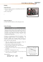
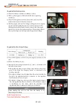
Charging
Procedure
●
Remove
the
battery
(see
Battery
Removal).
●
Connect
a
charger
to
the
battery
BEFORE
plugging
it
in
or
turning
it
on.
●
Set
the
charging
rate
and
time
according
to
the
battery
condition
previously
determined
CAUTION
Always
remove
the
battery
from
the
vehicle
for
charging.
Do
not
use
a
high
rate
battery
charger,
as
is
typically
employed
at
automotive
service
stations,
unless
the
charger
rate
can
be
reduced
to
the
level
required.
Charging
the
battery
at
a
rate
higher
than
specified
may
ruin
the
battery.
Charging
at
a
high
rate
causes
excess
heat,
which
can
warp
the
plates
and
cause
internal
shorting.
Higher
‐
than
‐
normal
charging
rates
also
cause
the
plates
to
shed
active
material.
Deposits
will
accumulate,
and
can
cause
internal
shorting.
●
Turn
the
charger
off
or
unplug
it,
then
disconnect
it
from
the
battery.
●
Check
battery
condition.
If
the
battery
condition
indicates
that
is
not
fully
charged,
additional
charging
time
is
necessary.
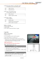
Battery
Test
Charging
●
If
the
battery
is
suspected
of
being
defective,
sulfated,
or
unable
to
take
a
charge,
consult
the
table.
●
To
test
charge
a
battery,
perform
the
ordinary
charging
procedure
and
monitor
the
battery
voltage
and
other
signs
as
mentioned
below.
If
the
battery
voltage
suddenly
jumps
to
over
13
V
just
after
the
start
of
charging,
the
plates
are
probably
sulfated.
A
good
battery
will
rise
to
12
V
immediately
and
then
gradually
go
up
to
12.5
or13
V
in
about
30
min.
to
an
hour
after
the
start
of
charging.
Summary of Contents for DL-702 2008
Page 1: ...FOREWORD INDEX 0 0...
Page 41: ...3 11 BRAKE...
Page 180: ...6 70 ENGINE Install the starter motor...
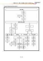
Page 201: ...7 21 COOLING AND LUBRICATION SYSTEM Engine Lubrication System Chart...
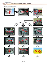
Page 202: ...7 22 COOLING AND LUBRICATION SYSTEM Engine Lubrication System 1 2 3 1 2 3 1 2 3...
Page 203: ...7 23 COOLING AND LUBRICATION SYSTEM 1 2 3...
Page 235: ...7 32 ELECTRICAL SYSTEM Wiring Diagram...
Page 236: ...7 33 ELECTRICAL SYSTEM Wiring Diagram...
Page 237: ...7 34 7 34 ELECTRICAL SYSTEM ELECTRICAL SYSTEM...
Page 238: ...7 35 ELECTRICAL SYSTEM NOTE...
Page 240: ...9 2 PERIODIC MAINTENANCE...
Page 246: ...9 8 PERIODIC MAINTENANCE Intake Side...
Page 247: ...9 9 PERIODIC MAINTENANCE Exhaust Side Side...
Page 270: ...9 32 PERIODIC MAINTENANCE 1 2 3 4 18 19 12 16 17 21 13 14 15 22 23 5 6 7 8 9 12 10 11 20...

