【
7-19
】
ELECTRICAL SYSTEM
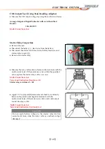
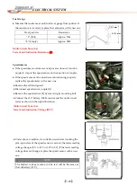
CDI
Output
Test:
(Using
Peak
Reading
Adaptor)
●
Measure
the
CDI
output
voltage
by
using
the
multi
‐
circuit
tester.
Average
Output
w/Digital
Voltmeter
with
or
without
Peak
Reader:
200~250
DCV
Multi
‐
Circuit
Tester
Set
Starter
Relay
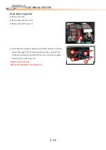
Inspection
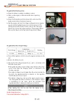
●
Remove
the
seat.
●
Disconnect
the
battery
(-
)
lead
wire
from
the
battery.
●
Disconnect
the
starter
motor
lead
wire,
battery
lead
wire
and
starter
relay
coupler
[1].
1
●
Remove
the
starter
relay.
●
Measure
the
relay
coil
resistance
between
the
terminals
with
the
multi
‐
circuit
tester.
If
the
resistance
is
not
within
the
specified
value,
replace
the
starter
relay
with
a
new
one.
Multi
‐
Circuit
Tester
Set
Tester
knob
indication:
Resistance
(
Ω
)
Starter
relay
resistance:
3
–
5
Ω
●
Apply
12
V
to
[A]
and
[B]
terminals
and
check
for
continuity
between
the
positive
and
negative
terminals
with
the
multi
‐
circuit
tester.
If
the
starter
relay
clicks
and
continuity
is
found,
the
relay
is
OK.
Multi
‐
Circuit
Tester
Set
Tester
knob
indication:
Continuity
test
CAUTION
Do
not
apply
battery
voltage
to
the
starter
relay
for
five
seconds
and
more,
since
the
relay
coil
may
overheat
and
get
damaged.
Summary of Contents for DL-702 2008
Page 1: ...FOREWORD INDEX 0 0...
Page 41: ...3 11 BRAKE...
Page 180: ...6 70 ENGINE Install the starter motor...
Page 201: ...7 21 COOLING AND LUBRICATION SYSTEM Engine Lubrication System Chart...
Page 202: ...7 22 COOLING AND LUBRICATION SYSTEM Engine Lubrication System 1 2 3 1 2 3 1 2 3...
Page 203: ...7 23 COOLING AND LUBRICATION SYSTEM 1 2 3...
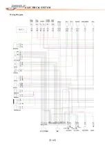
Page 235: ...7 32 ELECTRICAL SYSTEM Wiring Diagram...
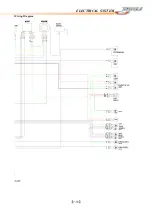
Page 236: ...7 33 ELECTRICAL SYSTEM Wiring Diagram...
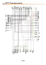
Page 237: ...7 34 7 34 ELECTRICAL SYSTEM ELECTRICAL SYSTEM...
Page 238: ...7 35 ELECTRICAL SYSTEM NOTE...
Page 240: ...9 2 PERIODIC MAINTENANCE...
Page 246: ...9 8 PERIODIC MAINTENANCE Intake Side...
Page 247: ...9 9 PERIODIC MAINTENANCE Exhaust Side Side...
Page 270: ...9 32 PERIODIC MAINTENANCE 1 2 3 4 18 19 12 16 17 21 13 14 15 22 23 5 6 7 8 9 12 10 11 20...

