【
7-22
】
ELECTRICAL SYSTEM
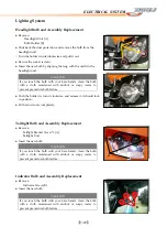
Combination
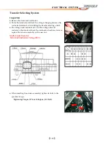
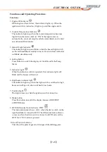
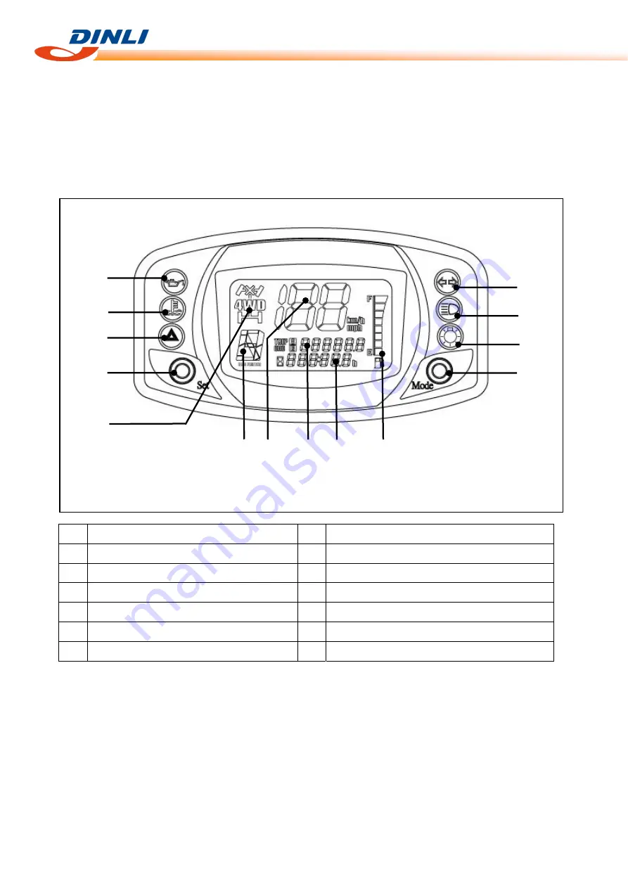
Meter
Description
●
This
combination
meter
mainly
consist
of
LCD
(Liquid
Crystal
Display)
and
LED
(Light
Emitting
Diode).
This
combination
meter
is
light,
thin
and
of
high
response
compared
to
those
currently
in
use
because
of
this
composition.
1
5
2
6
3
4
7
8
13
9
10
11
14
12
Mode
Button
1
8
Engine
Oil
Indicator
Coolant
Temperature
Indicator
4WD/
Differential
Lock
Indicator
2
9
Hazard
Light
Indicator
Gear
Position
Indicator
3
10
Setting
Button
Speedometer
4
11
Indicator
Light
ODO/TRIP
meter
5
12
Clock/Hour/Temp/Tacho
Meter
6
13
High
Beam
Indicator
Position
Light
Fuel
Meter
7
14
Summary of Contents for DL-702 2008
Page 1: ...FOREWORD INDEX 0 0...
Page 41: ...3 11 BRAKE...
Page 180: ...6 70 ENGINE Install the starter motor...
Page 201: ...7 21 COOLING AND LUBRICATION SYSTEM Engine Lubrication System Chart...
Page 202: ...7 22 COOLING AND LUBRICATION SYSTEM Engine Lubrication System 1 2 3 1 2 3 1 2 3...
Page 203: ...7 23 COOLING AND LUBRICATION SYSTEM 1 2 3...
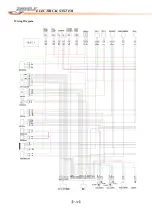
Page 235: ...7 32 ELECTRICAL SYSTEM Wiring Diagram...
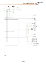
Page 236: ...7 33 ELECTRICAL SYSTEM Wiring Diagram...
Page 237: ...7 34 7 34 ELECTRICAL SYSTEM ELECTRICAL SYSTEM...
Page 238: ...7 35 ELECTRICAL SYSTEM NOTE...
Page 240: ...9 2 PERIODIC MAINTENANCE...
Page 246: ...9 8 PERIODIC MAINTENANCE Intake Side...
Page 247: ...9 9 PERIODIC MAINTENANCE Exhaust Side Side...
Page 270: ...9 32 PERIODIC MAINTENANCE 1 2 3 4 18 19 12 16 17 21 13 14 15 22 23 5 6 7 8 9 12 10 11 20...

